SUPER SC812L CHASSIS SERIES SC812L-U SC812L SC812L-520U SC812L-280U SC812L-520 SC812L-420 SC812L-520C SC812L-420C SC812L-410 USER’S MANUAL 1.
SC812L Chassis Manual The information in this User’s Manual has been carefully reviewed and is believed to be accurate. The vendor assumes no responsibility for any inaccuracies that may be contained in this document, makes no commitment to update or to keep current the information in this manual, or to notify any person or organization of the updates. Please Note: For the most up-to-date version of this manual, please see our web site at www.supermicro.com.
Preface Preface About This Manual This manual is written for professional system integrators and PC technicians. It provides information for the installation and use of the SC812L chassis. Installation and maintenance should be performed by experienced technicians only. Supermicro’s SC812L 1U chassis features a unique and highly-optimized design for dual-core Xeon platforms. The chassis is equipped with a high efficiency power supply for superb power savings.
SC812L Chassis Manual Notes iv
Preface Manual Organization Chapter 1: Introduction The first chapter provides a checklist of the main components included with this chassis and describes the main features of the SC812L chassis. This chapter also includes contact information. Chapter 2: System Safety This chapter lists warnings, precautions, and system safety. You should thoroughly familiarize yourself with this chapter for a general overview of safety precautions that should be followed before installing and servicing this chassis.
SC812L Chassis Manual Compatible Backplanes This section lists compatible cables, power supply specifications, and compatible backplanes. Not all compatible backplanes are listed. Refer to our Web site for the latest compatible backplane information.
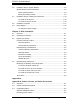
Preface Table of Contents Preface About This Manual ............................................................................................. iii Manual Organization ...........................................................................................v Chapter 1: Introduction 1-1 Overview ......................................................................................................... 1-1 1-2 Shipping List................................................................................
SC812L Chassis Manual 4-6 Installation Step 4: System Blowers ............................................................... 4-8 System Blower General Information ............................................................... 4-8 Blower Default Position .............................................................................. 4-9 Blower Secondary Position ........................................................................ 4-9 4-7 Installation Step 5: Installing the Air Shroud ...............
Preface Front Panel to the Motherboard ......................................................................A-3 A-4 Chassis Screws...............................................................................................
SC812L Chassis Manual Notes x
Chapter 1: Introduction Chapter 1: Introduction 1-1 Overview Supermicro’s SC812L chassis features a unique and highly-optimized design. The chassis is equipped with high efficiency power supply. High performance fans provide ample optimized cooling for FB-DIMM memory modules and four hot-swap drive bays offer maximum storage capacity. 1-2 Shipping List Part Numbers Please visit the following link for the latest shipping lists and part numbers for your particular chassis model http://www.supermicro.
SC812L Chassis Manual 1-3 Where to get Replacement Components Though not frequently, you may need replacement parts for your system. To ensure the highest level of professional service and technical support, we strongly recommend purchasing exclusively from our Supermicro Authorized Distributors / System Integrators / Resellers. A list of Supermicro Authorized Distributors / System Integrators /Reseller can be found at: http://www.supermicro.com. Click the Where to Buy link.
Chapter 1: Introduction 1-4 Contacting SuperMicro Headquarters Address: SuperMicro Computer, Inc. 980 Rock Ave. San Jose, CA 95131 U.S.A. Tel: +1 (408) 503-8000 Fax: +1 (408) 503-8008 Email: marketing@supermicro.com (General Information) support@supermicro.com (Technical Support) Web Site: www.supermicro.com Europe Address: SuperMicro Computer B.V. Het Sterrenbeeld 28, 5215 ML 's-Hertogenbosch, The Netherlands Tel: +31 (0) 73-6400390 Fax: +31 (0) 73-6416525 Email: sales@supermicro.
SC812L Chassis Manual Notes 1-4
Chapter 2: System Safety Chapter 2: System Safety 2-1 Overview This chapter provides a quick setup checklist to get your chassis up and running. Following the steps in order given should enable you to have your chassis setup and operational within a minimal amount of time. This quick set up assumes that you are an experienced technician, familiar with common concepts and terminology.
SC812L Chassis Manual l Do not work alone when working with high voltage components. l Power should always be disconnected from the system when removing or installing main system components, such as the serverboard, memory modules and the DVD-ROM and floppy drives (not necessary for hot swappable drives). When disconnecting power, you should first power down the system with the operating system and then unplug the power cords from all the power supply modules in the system.
Chapter 2: System Safety l Place the chassis top cover and any system components that have been removed away from the system or on a table so that they won’t accidentally be stepped on. l While working on the system, do not wear loose clothing such as neckties and unbuttoned shirt sleeves, which can come into contact with electrical circuits or be pulled into a cooling fan.
SC812L Chassis Manual l When handling chips or modules, avoid touching their pins. l Put the serverboard and peripherals back into their antistatic bags when not in use. l For grounding purposes, make sure your computer chassis provides excellent conductivity between the power supply, the case, the mounting fasteners and the serverboard.
Chapter 3: System Interface Chapter 3: System Interface 3-1 Overview There are several LEDs on the control panel as well as others on the drive carriers to keep you constantly informed of the overall status of the system as well as the activity and health of specific components. This chapter explains the meanings of all LED indicators and the appropriate response you may need to take.
SC812L Chassis Manual 3-2 Control Panel Buttons There are two push-buttons located on the front of the chassis. These are (in order from left to right) a reset button and a power on/off button. l Reset: The reset button is used to reboot the system. l Power: The main power switch is used to apply or remove power from the power supply to the server system. Turning off system power with this button removes the main power but keeps standby power supplied to the system.
Chapter 3: System Interface l NIC2: Indicates network activity on GLAN2 when flashing. l NIC1: Indicates network activity on GLAN1 when flashing. l HDD: Indicates IDE channel activity. SAS/SATA drive, SCSI drive, and/or DVD-ROM drive activity when flashing. l Power: Indicates power is being supplied to the system's power supply units. This LED should normally be illuminated when the system is operating.
SC812L Chassis Manual Notes 3-4
Chapter 4: Chassis Setup and Maintenance Chapter 4: Chassis Setup and Maintenance 4-1 Overview This chapter covers the steps required to install components and perform maintenance on the chassis. The only tool you will need to install components and perform maintenance is a Phillips screwdriver. Print this page to use as a reference while setting up your chassis. 4-2 Installation Steps 4-3 Installation Step 1: Remove the Chassis Cover .......................................
SC812L Chassis Manual 4-3 Installation Step 1: Remove the Chassis Cover 3 1 2 1 Release Tab Figure 4-1: Removing the Chassis Cover To remove the chassis cover: 1. Press the release tabs to remove the cover from the locked position. Press both tabs at the same time. 2. Once the top cover is released from the locked position, slide the cover toward the rear of the chassis. 3. Lift the cover off the chassis.
Chapter 4: Chassis Setup and Maintenance 4-4 Installation Step 2: Install Hard Drives Hard Drive Bracket Figure 4-2: Remove the Hard Drive To install a hard drive to the chassis: 1. Locate the hard drive bracket. 2. Remove the screw securing the bracket to the chassis and slide the bracket toward the rear of the chassis. 3. Connect a standard hard drive to the bracket and secure the connection with the four screws connected to the bracket. NOTE: The bracket includes four screws and four rubber feet.
SC812L Chassis Manual 4-5 Installation Step 3: Installing the Motherboard Riser Bracket Card Figure 4-4: Riser Card Bracket Permanent and Optional Standoffs Standoffs prevent short circuits by securing space between the motherboard and the chassis surface. The SC812L chassis includes permanent standoffs in locations used by most motherboards. These standoffs accept the rounded Phillips head screws included in the SC812L accessories packaging.
Chapter 4: Chassis Setup and Maintenance To install the motherboard: 1. Review the documentation that came with your motherboard. Become familiar with component placement, requirements, precautions, and cable connections. 2. Open the chassis cover. 3. Remove the riser card bracket. 4. As required by your motherboard, install standoffs in any areas that do not have a permanent standoff. To do this: A. Place a hexagonal standoff screw through the bottom the chassis. B.
SC812L Chassis Manual Add-on Card/Expansion Slot Setup SC812L chassis includes I/O slots for add-on cards and expansion cards. The number of cards you can use depends on your chassis model. SC812L chassis includes one full length/full height and one low profile add-on card slot. SC812L models "C" models include one full length/full height slot. SC812L "U" models include two full height/full length add-on card slots and one low-profile slot.
Chapter 4: Chassis Setup and Maintenance Riser Card Bracket Riser Card Figure 4-6: SC812L Riser Card and Bracket 4. Confirm that each add-on card you want use has an "L" bracket and connect each add-on card to the riser card embedded in the riser card bracket. 5. Re-connect the riser card (with add-on cards) to the motherboard. 6. Secure each card to the chassis using the card's L bracket and close the addon card shield clip. 7.
SC812L Chassis Manual 4-6 Installation Step 4: System Blowers Two heavy duty blowers provide cooling for the chassis. These blowers circulate air through the chassis as a means of lowering the chassis internal temperature. System Blower Blower Rack Blower Post Figure 4-17: Un-assembled System Blowers System Blower General Information When using the SC812L chassis be aware of the following: • The blower rack for the SC812L can be adjusted into two different positions: Left and Right.
Chapter 4: Chassis Setup and Maintenance The Left Blower is turned toward the rear of the chassis Foam Barrier Foam Barrier The Right Blower is angled to the side Figure 4-8: System Blowers in default position Blower Default Position With most compatible SuperMicro motherboards, the blowers remain in the default position. The default position is the tray in the furthest right position. The left blower is directed toward the rear of the chassis. The right blower is turned to the left.
SC812L Chassis Manual 4-7 Installation Step 5: Installing the Air Shroud Figure 4-9: Air Shroud for SC812L Chassis Air shrouds concentrate airflow to maximize blower efficiency. The SC812L accessory package includes the air shroud used by most motherboards. Alternate air shrouds are available for purchase. Check the motherboard documentation for more information To install the air shroud: Place the air shroud in the chassis. The air shroud fits behind the two blowers closest to the power supply.
Chapter 4: Chassis Setup and Maintenance 4-8 Installation Complete In most cases, the chassis power supply and blowers are pre-installed. If you need to install blowers continue to the Systems Blower section of this chapter. If the chassis will be installed into a rack, continue to the next chapter for rack installation instructions.
SC812L Chassis Manual 4-9 Power Supply Depending on your chassis model the SC812L Chassis has a 280, 410, 420, or 520 watt power supply. This power supply is auto-switching capable. This enables it to automatically sense and operate at a 100v to 240v input voltage. New units can be ordered directly from Supermicro (see contact information in the Preface). Remove these rear screws Figure 4-10: Chassis Power Supply To change the power supply: 1. Power down the server and unplug the power cord. 2.
Chapter 5: Rack Installation Chapter 5: Rack Installation 5-1 Overview This chapter provides simple instructions for installing this chassis into a rack. 5-2 Unpacking the System You should inspect the box the chassis was shipped in and note if it was damaged in any way. If the chassis itself shows damage you should file a damage claim with the carrier who delivered it. Decide on a suitable location for the rack unit that will hold your chassis.
SC812L Chassis Manual ! Warnings and Precautions ! - Ensure that the leveling jacks on the bottom of the rack are fully extended to the floor with the full weight of the rack resting on them. - In single rack installation, stabilizers should be attached to the rack. - In multiple rack installations, the racks should be coupled together. - Always make sure the rack is stable before extending a component from the rack.
Chapter 5: Rack Installation for safe operation is not compromised. Mechanical Loading Equipment should be mounted into a rack so that a hazardous condition does not arise due to uneven mechanical loading. Circuit Overloading Consideration should be given to the connection of the equipment to the power supply circuitry and the effect that any possible overloading of circuits might have on overcurrent protection and power supply wiring.
SC812L Chassis Manual 5-4 Rack Mounting Instructions This section provides information on installing the SC812L chassis into a rack unit with the rails provided. There are a variety of rack units on the market, which may mean the assembly procedure will differ slightly. You should also refer to the installation instructions that came with the rack unit you are using. NOTE: The rails will fit a rack between 29" and 35.25" deep.
Chapter 5: Rack Installation A B C Figure 5-1: Inner and Outer Rails To separate the inner and outer rails: 1. Pull the inner rail (A) from the outer rail (B) as far as possible. 2. Depress the locking tab (C) to pull the inner rail completely out. 3. Repeat steps 1 and 2 for the other rail. Inner Chassis Rail Figure 5-2: Rail Installation To install the inner rail to the chassis: 1. Align the chassis rail with the side of the chassis. 2. Secure the rail to the chassis using six M5 flat head screws.
SC812L Chassis Manual Outer Rails Rail Brackets Figure 5-3. Rack Brackets To install the outer rails to the rack: 1. Confirm that the inner rails have been separated from the outer rails. 2. Locate the rail brackets in the accessories box. The chassis package includes four rail brackets and two chassis mounts. The rail brackets have long ovals used to adjust the position of the rails when mounting. The chassis mounts (both short) have one square hole. 3.
Chapter 5: Rack Installation Rail Bracket B C A Figure 5-3.
SC812L Chassis Manual To install the chassis into a rack: 1. Confirm that the chassis includes the inner rails (A) and that the outer rails (B) are installed on the rack (See Figure 5-3) 2. Align the chassis rails (A) with the front of the rack rails (C). 3. Slide the chassis rails into the rack rails, keeping the pressure even on both sides (you may have to depress the locking tabs when inserting). When the server has been pushed completely into the rack, you should hear the locking tabs "click". 4.
Chapter 5: Rack Installation Telco (Two Post) Racks Telco racks utilize two posts instead of four. Because of this, telco racks require a different installation process. Outer Rails Chassis Mounts Rail Brackets Figure 5-4: Installing the Server into a Telco Rack To install the chassis into a Telco rack: This chassis requires both the inner and outer rails for Telco rack installation. You must reverse the brackets to accommodate two posts instead of four: 1.
SC812L Chassis Manual Figure 5-6: Installing the Server into a Telco Rack 5. Place one outer rail in the Telco rack as illustrated. 6. Slide the brackets until each snugly fits against the Telco rack post. 7. Secure the brackets to the Telco rack with two M5 screws for each bracket. 8. Tighten the M4 screws that secure each bracket to the outer rail. 9. Repeat steps 5 - 9 using the second outer rail. 10. Line the inner chassis rails (A) with the front of the outer rails (C) (see Figure 5-3). 11.
Chapter 5: Rack Installation 12. (Optional) If you installed the front chassis mount, you can insert thumbscrews through the chassis ears and chassis mounts. The chassis cannot be pulled from the rack unless the thumbscrews are removed.
SC812L Chassis Manual Notes 5-12
Appendices Appendices Appendix A: Compatible Cables 1
SC812L Chassis Manual Notes 2
Appendix A: Chassis Cables Appendix A: Cables, Screws, and Other Accessories A-1 Overview This appendix lists supported cables for your chassis system. It only includes the most commonly used components and configurations. For more compatible cables, refer to the manufacturer of the motherboard you are using and our Web site at: www.supermicro.com.
SC812L Chassis Manual A-3 Compatible Cables Alternate SAS/SATA Cables Some compatible motherboards may have different connectors. If your motherboard has only one SAS connector that the SAS/SATA cables must share, use one of the following cables. These cables must be purchased separately. Cable Name: SAS Cable Quantity: 1 Part #: CBL-0175L Alt. Name: "Big Four" Description: This cable has one SFF-8484 (32 pin) connector on one end and 4 SAS connectors (7 pins each) at the other.
Appendix A: Chassis Cables Extending Power Cables Although Super Micro chassis are designed with to be efficient and cost-effective, some compatible motherboards have power connectors located in different areas. To use these motherboards you may have to extend the power cables to the mother boards. To do this, use the following chart as a guide. Power Cable Extenders Number of Pins Cable Part # Length 24 pin CBL - 0042 7.9”(20 CM) 20 pin CBL - 0059 7.9”(20 CM) 8 pin CBL - 0062 7.
SC812L Chassis Manual A-4 Chassis Screws The Chassis and accessory box include all the screws needed to setup your chassis. This section include descriptions of the most common screws used. Your chassis may not require all the parts listed. M/B HARD DRIVE Flat head 6-32 x 5 mm [0.197] Pan head 6-32 x 5 mm [0.197] DVD-ROM, CD-ROM, and FLOPPY DRIVE Pan head 6-32 x 5 mm [0.197] Flat head 6-32 x 5 mm [0.197] Round head M3 x 5 mm [0.197] Round head M2.6 x 5 mm [0.197] RAIL Flat head M4 x 4 mm [0.