
User's and BIOS Manual (1.0)


2-4
AS1011M-T2 User's Manual
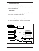
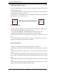
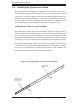
Figure 2-1. Identifying the Sections of the Rack Rails
A
B
2-4 Installing the System into a Rack
This section provides information on installing the 1011M-T2 into a rack unit. If
the system has already been mounted into a rack, you can skip ahead to Sections
2-5 and 2-6. There are a variety of rack units on the market, which may mean the
assembly procedure will differ slightly. The following is a guideline for installing the
unit into a rack with the rack rails provided with the system. You should also refer
to the installation instructions that came with the rack unit you are using.
Identifying the Sections of the Rack Rails
You should have received two rack rail assemblies with the 1011M-T2. Each of
these assemblies consist of two sections: an inner fi xed chassis rail that secures to
the unit (A) and an outer fi xed rack rail (B) that secures to the rail brackets. A sliding
rail guide sandwiched between the two should remain attached to the fi xed rack rail
(see Figure 2-1). The A and B rails must be detached from each other to install.
To remove the fi xed chassis rail (A), pull it out as far as possible - you should hear
a "click" sound as a locking tab emerges from inside the rail assembly and locks
the inner rail. Then depress the locking tab to pull the inner rail completely out.
Do this for both the left and right side rack rail assemblies.
Pull out the inner
rail(to be attached
on the chassis)
Outer rail (to be
installed in the
rack)