
User's and BIOS Manual (1.0)

Chapter 5: Advanced Serverboard Setup
5-7
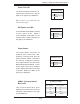
5-5 I/O Ports
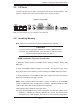
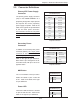
The I/O ports are color coded in conformance with the PC 99 specifi cation. See
Figure 5-4 below for the colors and locations of the various I/O ports.
Figure 5-4. I/O Ports
5-6 Installing Memory
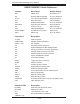
Note: Check the our web site for recommended memory modules.
CAUTION
Exercise extreme care when installing or removing DIMM modules
to prevent any possible damage. Also note that the memory is inter-
leaved to improve performance (see step 1).
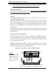
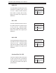
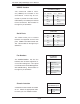
DIMM Installation (Figures 5-5a and 5-5b)
1. Insert the desired number of DIMMs into the memory sockets, starting with
Bank #1A.
2. Insert each DIMM module vertically into its socket. Pay attention to the notch
along the bottom of the module to prevent inserting the DIMM module incorrectly.
3. Gently press down on the DIMM module until it snaps into place in the sockets.
Repeat for all modules (see step 1 above).
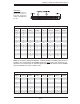
Notes: each processor has its own built-in memory controller, so CPU2 DIMMs
cannot be addressed if only a single CPU is installed. 128 MB, 256 MB, 512 MB,
1 GB, 2 GB* and 4 GB* memory modules are supported.
*With Opteron 246 C-stepping CPUs and above.
It is highly recommended that you remove the power cord from the system before
installing or changing any memory modules. each socket, but has only been
verifi ed for up to 1 GB modules. The memory is an interleaved confi guration,
Note: The external SCSI port is not included on the 1020P-T(R).