
User's and BIOS Manual (1.0)

5-16
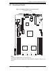
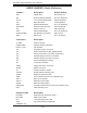
AS1020P-T(R)/1020P-8(R) User's Manual
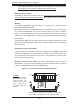
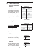
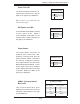
Fan Headers
The H8DSP/H8DSP-i has five fan
headers, each of which support two 4-
cm counter-rotating fans. Fan speed
is controlled via Thermal Management
with a BIOS setting. See the table on
the right for pin defi nitions.
Serial Ports
The COM1 serial port is located
between the keyboard and the LAN
ports. COM2 is a header located near
JD1. See the table on the right for pin
defi nitions.
Note: NC indicates no connection.
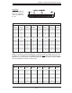
Serial Port Pin Defi nitions
(COM1/COM2)
Pin # Defi nition Pin # Defi nition
1CD 6DSR
2RD 7RTS
3TD 8CTS
4 DTR 9 RI
5 Ground 10 NC
Fan Header
Pin Defi nitions
(FAN1/2-9/10)
Pin# Defi nition
1 FAN2 Power
2 FAN2 Tachometer
3 Ground
4 Ground
5 FAN1 Tachometer
6 FAN1 Power
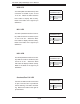
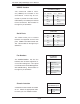
USB2/3 Headers
Two additional USB2.0 head-
ers (USB2/3) are included on the
serverboard. These may be con-
nected to provide front side access.
USB cables (not included) are needed
for the connections. See the table on
the right for pin defi nitions.
Extra Universal Serial Bus Headers
Pin Defi nitions (USB2/3)
USB2
Pin # Defi nition
USB3/4
Pin # Defi nition
1 +5V 1 +5V
2 PO- 2 PO-
3 PO+ 3 PO+
4 Ground 4 Ground
5 Key 5 No connection
Chassis Intrusion
A Chassis Intrusion header is located
at JL1. Attach the appropriate cable
to inform you of a chassis intrusion.
Chassis Intrusion
Pin Defi nitions (JL1)
Pin# Defi nition
1 Intrusion Input
2 Ground