SUPER JP69 5 UPGRADE U24 JP53 1 1 SB#2 JP95 A R603 JP84 3 R589 8 1 1 JP84:MODE 1-2:SGPIO 2-3:I2C JP51 SB#1 JP37 I2C#1 SAS213LTQ 7 REV: 1.
SAS-213LTQ Backplane User's Guide The information in this User’s Manual has been carefully reviewed and is believed to be accurate. The vendor assumes no responsibility for any inaccuracies that may be contained in this document, makes no commitment to update or to keep current the information in this manual, or to notify any person or organization of the updates. Please Note: For the most up-to-date version of this manual, please see our web site at www.supermicro.com. Super Micro Computer, Inc.
Safety Information and Technical Specifications Table of Contents Contacting Supermicro........................................................................................iv Chapter 1 Safety Guidelines 1-1 ESD Safety Guidelines.................................................................................... 2-1 1-2 General Safety Guidelines............................................................................... 2-1 1-3 A Note to Users.....................................................
SAS-213LTQ Backplane User's Guide Contacting Supermicro Headquarters Address: Super Micro Computer, Inc. 980 Rock Ave. San Jose, CA 95131 U.S.A. Tel: +1 (408) 503-8000 Fax: +1 (408) 503-8008 Email: marketing@supermicro.com (General Information) support@supermicro.com (Technical Support) Web Site: www.supermicro.com Europe Address: Super Micro Computer B.V. Het Sterrenbeeld 28, 5215 ML 's-Hertogenbosch, The Netherlands Tel: +31 (0) 73-6400390 Fax: +31 (0) 73-6416525 Email: sales@supermicro.
Safety Information and Technical Specifications Returning Merchandise for Service A receipt or copy of your invoice marked with the date of purchase is required before any warranty service will be rendered. You can obtain service by calling your vendor for a Returned Merchandise Authorization (RMA) number. When returning to the manufacturer, the RMA number should be prominently displayed on the outside of the shipping carton, and mailed prepaid or hand-carried.
SAS-213LTQ Backplane User's Guide Notes 1-2
Safety Information and Technical Specifications Chapter 1 Safety Guidelines To avoid personal injury and property damage, carefully follow all the safety steps listed below when accessing your system or handling the components. 1-1 ESD Safety Guidelines Electrostatic Discharge (ESD) can damage electronic components. To prevent damage to your system, it is important to handle it very carefully. The following measures are generally sufficient to protect your equipment from ESD.
SAS-213LTQ Backplane User's Guide 1-3 • 1-4 A Note to Users All images and layouts shown in this user's guide are based upon the latest PCB revision available at the time of publishing. The card you have received may or may not look exactly the same as the graphics shown in this manual. Introduction to the SAS-213LTQ Backplane The SAS-213LTQ backplane has been designed to utilize the most up-to-date technology available, providing your system with reliable, high-quality performance.
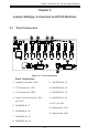
Safety Information and Technical Specifications Chapter 2 Jumper Settings, Connectors and Pin Definitions 2-1 Front Connectors 15 1 1 JP69 5 UPGRADE U24 JP95 2 A JP84 R603 3 R589 8 R607 C I2C#2 1 7 1 JP84:MODE 1-2:SGPIO 2-3:I2C JP51 SB#1 12 JP37 I2C#1 SAS213LTQ 7 REV: 1.
SAS-213LTQ Backplane User's Guide 2-2 Front Connector and Pin Definitions 1. Upgrade Connectors The upgrade connector is designated JP69 and is used for manufacturer's diagnostic purposes only. 2. - 3. I2C Connectors I2C Connector Pin Definitions The I2C Connectors, designated JP37 andJP95, are used to monitor HDD activity and status. See the table on the right for pin definitions. Pin# Definition 1 Data 2 Ground 3 Clock 4 No Connection 4.
Safety Information and Technical Specifications 14. - 15. Sideband #1 and #2: Sideband Headers The sideband headers are designated JP51 and JP53. For SES-2 to work properly, an 8-pin sideband cable must be connected. See the table on the right for pin definitions.
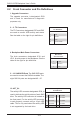
SAS-213LTQ Backplane User's Guide 2-3 Front Jumper Locations and Pin Definitions JP84 JP69 5 UPGRADE U24 SB#2 JP95 2 C A R603 JP84 3 R589 8 R607 JP51 1 1 JP84:MODE 1-2:SGPIO 2-3:I2C SB#1 JP37 I2C#1 SAS213LTQ 7 REV: 1.
Safety Information and Technical Specifications I2C and SGPIO Modes and Jumper Settings This backplane can utilize I2C or SGPIO. SGPIO is the default mode and can be used without making changes to your jumper. The following information details which jumper must be configured to use SGPIO mode or restore your backplane to I2C mode.
P69 UPGRADE U24 1 SAS-213LTQ Backplane User's Guide 2 5:9072 RST :RST :NO RST JP53 1 SB#2 JP95 MH2 2 Front LED Indicators C A I2C 7 8 R607 R603 C100 D3 ALARM J14 J16 Y1 P35 JP69 5 UPGRADE U24 JP53 1 1 SB#2 JP95 8 R603 3 1 1 JP84:MODE 1-2:SGPIO 2-3:I2C 7 C100 JP51 SB#1 JP37 I2C#1 SAS213LTQ 7 REV: 1.
Safety Information and Technical Specifications SAS213LTQ SAS/SATA #7 SAS/SATA #6 SAS/SATA #5 SAS/SATA #4 SAS/SATA #3 SAS/SATA #1 SAS/SATA #2 Rear Connectors and LED Indicators SAS/SATA #0 2-4 REV: 1.
SAS-213LTQ Backplane User's Guide Disclaimer (cont.) The products sold by Supermicro are not intended for and will not be used in life support systems, medical equipment, nuclear facilities or systems, aircraft, aircraft devices, aircraft/emergency communication devices or other critical systems whose failure to perform be reasonably expected to result in significant injury or loss of life or catastrophic property damage.