
User's Guide (1.0)


2-4
SAS-213LTQ Backplane User's Guide
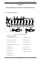
2-2 Front Connector and Pin Denitions
1. Upgrade Connectors
The upgrade connector is designated JP69
and is used for manufacturer's diagnostic
purposes only.
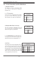
2. - 3. I
2
C Connectors
The I
2
C Connectors, designated JP37 andJP95,
are used to monitor HDD activity and status.
See the table on the right for pin denitions.
I
2
C Connector
Pin Denitions
Pin# Denition
1 Data
2 Ground
3 Clock
4 No Connection
Backplane
Main Power
4-Pin Connector
Pin# Denition
1
+12V
2 and 3
Ground
4 +5V
4. Backplane Main Power Connectors
The 4-pin connectors, designated JP10, and
JP13, provide power to the backplane. See the
table on the right for pin denitions.
5. - 12. SAS/SATA Ports The SAS/SATA ports
are used to connect the SAS drive cables. The
eight SAS IN ports are designated #0 - #7.
13. ACT_IN:
The activity LED connector designated JP26, is
used to indicate the activity status of each SAS
drive. The activity LED connector is located on
the front panel. For the activity LED connector
to work properly, connect using a 10-pin LED
cable. This is only used when the activity LED
is not supported by the hard drive.
SAS Activity LED Header
Pin Denitions
Pin# Denition Pin# Denition
1 ACT IN#0 6 ACT IN#4
2 ACT IN#1 7 ACT IN#5
3 ACT IN#2 8 ACT IN#6
4 ACT IN#3 9 ACT IN#7
5 Ground X Empty