SUPER The SC512C/L Series The SC512C Series The SC512L Series SC512 CHASSIS USER'S GUIDE 1.
SC512 Chassis User’s Guide The information in this User’s Guide has been carefully reviewed and is believed to be accurate. The vendor assumes no responsibility for any inaccuracies that may be contained in this document, makes no commitment to update or to keep current the information in this manual, or to notify any person or organization of the updates. Please Note: For the most up-to-date version of this manual, please see our web site at www.supermicro.com.
Chapter 1: Safety Information and Technical Specifications Table of Contents Chapter I: Safety Information and Technical Specifications ................ 1-4 1-1. Electrical Safety Guidelines ............................................................................ 1-4 1-2. ESD Safety Guidelines ..................................................................................... 1-4 1-3. General Safety Guidelines ............................................................................... 1-5 1-4.
SC512 Chassis User’s Guide Chapter 1- Introduction 1-1 Electricity Safety General Electrical Safety Guidelines ! • Use the exact type of power cords as required. • Be sure to use power cord(s) that came with safety certifications. • The power cord(s) must be compliant with the AC voltage requirements in your region. • Plug the Power cord(s) into a socket that is properly grounded before turning on the power. • Take extra precautionary measures when working with high voltage components.
Chapter 1: Safety Information and Technical Specifications 1-3. General Safety Guidelines ! • Warning!! Follow the guidelines below to avoid possible damage to the system or injury to yourself: To avoid injuries to your back, be sure to use your leg muscles, keep your back straight, and bend your knees, when lifting the system. • After removing the components or chassis covers from the system, place them on a table for safeguard.
SC512 Chassis User’s Guide 1-6 Product Compliance Information If integrated with a motherboard validated and recommended by Supermicro, and configured based upon the instructions outlined in this manual, the SC512 Chassis is compliant with the following safety standards/requirements: Product Safety *Canada/USA--UL60 950-CSA60 950 *European Union--EN 60 950 *International--IEC 60 950 (*Power Supply only) Electromagnetic Compatibility (EMC)-Emissions *European Union--EN55022: 1994 *International--CISPR 22 *U
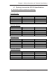
Chapter 1: Safety Information and Technical Specifications 1-7. Packing List and the SC512 Specifications A. The SC512 chassis contains the following: The SC512L Series: Component Blower HDD USB Floppy CD-ROM Power Qty One (3800rpm blower) Two 3.5” Drives N/A N/A N/A 200W Part Number FAN-0038 ----PWS-0043 Qty One (5000rpm blower) Two 3.5” Drives N/A N/A N/A 260W Part Number FAN-0059 ----PWS-0055 Qty One (3800rpm blower) One 3.5” Drive One 2.
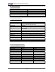
SC512 Chassis User’s Guide B. The Accessory Kit Component AC Power Cord Screws Rackmount Kit SC512 I/O Label Hard Disk Drive Mounting Kit Air Shroud Quantity 1 1 set 1 (CSE-PT8) –(*optional) 2 1 1 C. Chassis Specifications Specifications Form Factor 14” mini 1U chassis support for maximum MB size: 12”x9.7” (304.7mmx 246.4mm) ATX CPU Support Pentium 4 Expansion Card One full-height/half-length PCI Slot (w/Riser Card) Drive Bays The SC512L Series: two 3.5” fixed, the SC512C Series: one 3.
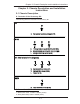
Chapter 2: Chassis Description and Installation Instructions Chapter 2: Chassis Description and Installation Instructions 2-1 Chassis Description A. Contents of the Accessory Kit: The following items are included in the Accessory Kit: C M/B A C. Thu HDD A. Pan head w/ lock 6-32 x 4.5 mm [0.177] DRIVE E B J B. Flat head 6-32 x 5 mm [0.197] (*For 3.5" HDD) E. Round head M3 x 5 mm [0.197] (*For 2.5" HDD) J. Hexagon head 6-32 x 5 mm [0.197] RAIL (*Not included in the shipment) G H I G.
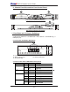
SC512 Chassis User’s Guide C. Chassis Front View and the Front Control Panel 1 2 3 The SC512C Chassis Front View 1 The SC512L Chassis Front View 1. Front Panel and I/O Device Definitions 1. Front Panel LED Indicators 2. I/O Devices (SC512C: 1 CD-ROM and 1 HDD, SC512L: 1 CD-ROM only) 3. USB ports (x2) 2. Front Panel LED Button Definitions 1 1e 1a. Power On LED 1c. NIC1 (LAN1) LED 1e. Overheat LED 1d 1c 1b 1a 1b. HDD Activity LED 1d. NIC2 (LAN2) LED 3.
Chapter 2: Chassis Description and Installation Instructions D. Chassis Rear View SC512 Chassis Rear View -B- 3 2 1 1. Back Panel and I/O Device Descriptions 1. Power Connector 2. COM Port 3.
SC512 Chassis User’s Guide 2-2 Chassis Installation A. Important Safety Guidelines STOP This product shall only be accessed, assembled and serviced by technically qualified personnel or technicians. To avoid personal injury and property damage, please read all the information provided in Chapter 1, and carefully follow all the Safety Guidelines listed before accessing or servicing the SC512 or its components.
Chapter 2: Chassis Description and Installation Instructions C. Removing the Top Chassis Cover and the HDD Tray Bracket from the chassis Before installing a hard drive into the chassis, you need to remove the top cover and the HDD tray bracket from the chassis. (*Note: Removing the top cover when the system is running will degrade thermal performance.) Procedures 1. Press the two tabs on the top cover to release the cover from the locking position. 2.
SC512 Chassis User’s Guide D1. Removing the CD-ROM Module Before installing a CD-ROM into the CD-ROM module, you need to remove the CD-ROM module from the chassis. Procedures 1. Remove the screw. 2. Once the screw is removed, slide the CD-ROM module toward the backplane to loosen it as shown in the picture below. 1 2 3. Once the module is loosened, remove it from the SC512 as shown below.
Chapter 2: Chassis Description and Installation Instructions D2. Removing the HDD Drive Tray Housing and Installing the HDDs After the HDD Drive Tray Bracket is removed from the chassis, you can install HDDs into the HDD Drive Housing. Procedures 1. Remove the four screws on the back of the chassis as shown in the picture. 2. Once the screws are removed, you can remove the HDD tray from the chassis.
SC512 Chassis User’s Guide E. Installing the Motherboard Be sure to disconnect the power supply before accessing or installing the motherboard into the chassis. (Refer to Chapter 1 for Safety Guidelines.) Procedures 1. Lay the chassis on a flat surface. 2. Locate the CPU location(s). If you have a UP system, be sure to install heatsink brackets on the reverse side of the CPU. (Ignore this step if you have a DP system.) 3.
Chapter 2: Chassis Description and Installation Instructions F. Installing and Uninstalling the Heatsink Mechanism Heatsinks are heavy. Please handle with care!! *Note: Be sure to use Heatsink # SNK-P0011 for a ! system, and use Heatsink #SNK-P0007 for a DP System. UP Procedures: Heatsink Installation 1. Do not apply any thermal grease to the heatsink or the CPU die; the required amount of thermal grease has already been applied. 2.
SC512 Chassis User’s Guide G. Installing the Cooling Fan Module and the Air Shroud After the motherboard and the heatsink(s) have been installed in the chassis, you need to install the cooling fans and an air shroud for proper system cooling. Procedures (*Installing the Cooling Fan Module) 1. Locate two pins on the bottom of the SC512 chassis. 2. Locate two holes on the fan module. 3. Align the two holes on the fan module against the two pins on the bottom of the SC512. 4.
Chapter 2: Chassis Description and Installation Instructions H. Installing Chassis Rails (*Optional) (*Note: if your chassis does not come with chassis rails, please follow the procedure listed on the last page to install the SC512 directly into the rack.) STOP Please make sure that the chassis covers and chassis rails are installed on the chassis before you install the chassis into the rack.
SC512 Chassis User’s Guide 3. Locate the three holes on each side of the chassis and locate the three corresponding holes on each of the inner rail. 3 G 4. Attach an inner rail to each side of the chassis and secure the inner rail to the chassis by inserting three Type G screws through the holes on each side of the chassis and the inner rail. (Refer to Page 2-1 for the Type G screw.) 5. Repeat the above steps to install the other rail on the chassis.
Chapter 2: Chassis Description and Installation Instructions I-1 Installing the Traditional UP Racks (*Optional) After you have installed the inner rails on the chassis, you are ready to install the outer rails of rail assemblies to the rack. (* The rails are designed to fit in the racks with the depth of 28" to 33".) Procedures 1. In the package, locate a pair of front (-short) and rear (-long) brackets. Please note that the brackets are marked with Up/Front Arrows (-front) and Up/Rear arrows (-rear). 2.
SC512 Chassis User’s Guide 7. Slide the SC512 chassis into the rack as shown below. (The SC512 may not slide into the rack smoothly or easily when installed the first time. Some adjustment to the slide assemblies might be needed for easy installation.) 8. You will need to release the safety taps on both sides of the chassis in order to completely remove the chassis out of the rack.
Chapter 2: Chassis Description and Installation Instructions I-2 Installing the Open-Racks (*Optional) After you have installed the inner rails on the chassis, you are ready to install the outer rails of rail assemblies to the rack. (* The rails are designed to fit in the racks with the depth of 28" to 33".) Procedures 1. In the package, locate a pair of front (-short) and rear (-long) brackets. Please note that the brackets are marked with Up/Front Arrows (-front) and Up/Rear arrows (-rear). 2.
SC512 Chassis User’s Guide 3. Attach the front (-short) bracket to the front end of the rack, and secure it to the rack with two Type H screws and Type I washers as shown below. 4. Attach the rear (-long) bracket to the rear end of the rack, and secure it to the rack with two Type H screws and Type I washers as shown below. Repeat the same steps to install the other outer rail to the other side of rack.
Chapter 2: Chassis Description and Installation Instructions 5. Measure the depth of your rack and adjust the length of the rails accordingly. Then, secure the rails to the chassis with Type G screws. 6. Slide the inner rails which are attached to the chassis into the outer rails on the rack.
SC512 Chassis User’s Guide J. Installing the SC512 into the Racks STOP Before installing the chassis into the rack: 1. Make sure that the rack is securely anchored onto a unmovable surface or structure before installing the chassis into the rack. 2. Unplug the power cord(s) of the rack before installing the chassis into the rack. 3. Make sure that the system is adequately supported. Make sure that all the components are securely fastened to the chassis to prevent components falling off from the chassis.