SAS M35TQ Mobile Rack USER'S GUIDE Rev. 1.
SAS M35TQ Mobile Rack User's Guide The information in this User’s Manual has been carefully reviewed and is believed to be accurate. The vendor assumes no responsibility for any inaccuracies that may be contained in this document, makes no commitment to update or to keep current the information in this manual, or to notify any person or organization of the updates. Please Note: For the most up-to-date version of this manual, please see our web site at www.supermicro.com. Super Micro Computer, Inc.
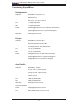
Safety Information and Technical Specifications Table of Contents SAS M35TQ Mobile Rack Contacting SuperMicro ..................................................................................................iv Returning Merchandise for Service ...............................................................................v Chapter 1: Safety Guidelines 1-1 ESD Safety Guidelines ................................................................................... 1-1 1-2 General Safety Guidelines .........
SAS M35TQ Mobile Rack User's Guide Contacting SuperMicro Headquarters Address: SuperMicro Computer, Inc. 980 Rock Ave. San Jose, CA 95131 U.S.A. Tel: +1 (408) 503-8000 Fax: +1 (408) 503-8008 Email: marketing@supermicro.com (General Information) support@supermicro.com (Technical Support) Web Site: www.supermicro.com Europe Address: SuperMicro Computer B.V. Het Sterrenbeeld 28, 5215 ML 's-Hertogenbosch, The Netherlands Tel: +31 (0) 73-6400390 Fax: +31 (0) 73-6416525 Email: sales@supermicro.
Safety Information and Technical Specifications Returning Merchandise for Service A receipt or copy of your invoice marked with the date of purchase is required before any warranty service will be rendered. You can obtain service by calling your vendor for a Returned Merchandise Authorization (RMA) number. When returning to the manufacturer, the RMA number should be prominently displayed on the outside of the shipping carton, and mailed prepaid or hand-carried.
Safety Information and Technical Specifications Chapter 1: Safety Guidelines To avoid personal injury and property damage, carefully follow all the safety steps listed below when accessing your system or handling the components. 1-1 ESD Safety Guidelines Electric Static Discharge (ESD) can damage electronic components. To prevent damage to your system, it is important to handle it very carefully. The following measures are generally sufficient to protect your equipment from ESD.
SAS M35TQ Mobile Rack User's Guide Notes 1-2
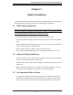
Safety Information and Technical Specifications Chapter 2: Jumpers Settings and Pin Definitions 2-1 Front Connectors and Jumpers 1 S UPER 2 3 R SASM35TQ 8 5 REV 1.01 4 7 9 11 12 13 14 15 6 10 Front Connectors 1. Power Connectors (4-pin): JP10 and JP13 2. Chip: MG 9072 8. Upgrade JP46 9. ACT IN JP26 10. FAN Connector JP22 3. JTAG JP47 11. SAS Port #0 J5 4. I2C Connector #1 JP44 12. SAS Port #1 J6 2 5. I C Connector#2 JP45 13. SAS Port #2 J7 6. SideBand Connector #1 JP51 14.
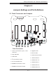
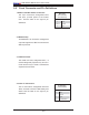
SAS M35TQ Mobile Rack User's Guide 2-2 Front Connector and Pin Definitions 1. Mobile rack Main Power Connectors Mobile rack Main Power 4-Pin Connector (JP10 and JP13) The 4-pin connectors, designated JP10 and JP13, provide power to the mobile rack. See the table on the right for pin Pin# Definition 1 definitions. +12V 2 and 3 4 Ground +5V 2. MG9072 Chip The MG9072 is an enclosure management chip that supports the SES-2 controller and SES-2 protocols. 3.
Safety Information and Technical Specifications 6 and 7. Sideband Headers Sideband Headers (JP51 and JP52) The sideband headers are designated JP51 and JP52. For SES-2 to work properly, you must connect an 8-pin sideband cable. See Pin # Definition Pin # Definition 2 Mobile rack Addressing (SB5) 1 Controller ID (SB6) 4 Reset (SB4) 3 GND (SB2) 6 GND (SB3) 5 SDA (SB1) 8 Mobile rack ID (SB7) 7 SCL (SB0) 10 No Connection 9 No Connection the table to the right for pin definitions. 8.
SAS M35TQ Mobile Rack User's Guide 2-3 Front Jumper Locations and Pin Definitions S UPER R SASM35TQ REV 1.01 S UPER JP62 JP38 JP29 R JP50 SASM35TQ JP36 JP41 JP40 JP33 JP37 JP43 JP61 JP34 REV 1.01 JP42 JP18 Explanation of Jumpers To modify the operation of the mobile rack, jumpers can be used to choose between optional settings. Jumpers create shorts between two pins to change the function of the connector. Pin 1 is identified with a square solder pad on the printed circuit board.
Safety Information and Technical Specifications Jumper Settings Jumper Jumper Settings Note JP18 Open: Enabled Closed: Disabled Buzzer Reset JP29 Open: Default Closed: Reset 9072 Chip Reset Fan Jumper Settings This mobile rack can use up to four fans. To utilize each fan, you must configure both jumpers as instructed below.
SAS M35TQ Mobile Rack User's Guide I2C and SGPIO Modes and Jumper Settings This mobile rack can utilize I2C or SGPIO. I2C is the default mode and can be used without making changes to your jumpers. The following information details which jumpers must be configured to use SGPIO mode or restore your mobile rack to I2C mode.
Safety Information and Technical Specifications SAS Port Connections in I2C and SGPIO Settings Use the following chart when connecting this mobile rack. If you connect the SAS ports out of order, you will not able to easily identify drives using the LED function.
SAS M35TQ Mobile Rack User's Guide SAS Rear Connectors and LED Indicators #0 2-4 FAIL #0 SAS #1 ACT #0 SAS #0 J1 SAS #1 J2 FAIL #1 SAS #2 ACT #1 SAS #2 J3 FAIL #2 SAS #3 SAS #3 J4 #4 ACT #2 SAS #4 J9 FAIL #3 SAS ACT #3 FAIL #4 SAS #4 ACT #4 FAN FAIL OH / DRIVE FAIL D4 Rear SAS/SATA Connectors Rear Connector SAS Drive Number SAS #0 SAS/SATA HHD #0 SAS #1 SAS/SATA HHD #1 SAS #2 SAS/SATA HHD #2 SAS #3 SAS/SATA HHD #3 SAS #4 SAS/SATA HHD #4 2-8 D3
Safety Information and Technical Specifications Rear LED Indicators Rear LED Hard Drive Activity Failure LED SAS #0 D12 D5 SAS #1 D13 D6 SAS #2 D14 D7 SAS #3 D15 D8 SAS #4 D18 D19 Mobile Rack Backplane LEDs LED D3 D4 Hard Drive Activity Failure LED ON Overheat/Drive Failure LED Indicator (Red light: flashing, Buzzer: On) ON Overheat/Drive Failure LED Indicator (Red light: flashing, Buzzer: On) 2-9
SAS M35TQ Mobile Rack User's Guide Notes 2-10
Safety Information and Technical Specifications Chapter 3: Installation Procedures 3-1 Tools Needed The following tools are neeed for the installation of the mobile rack into the chassis: • Phillips head screwdriver • Antistatic Strap (recommended) 3-2 Important Safety Guidelines This product should be assembled and/or serviced by qualified and experienced technicians. To avoid personal injury and property damage, carefully follow the guidelines listed below. Before accessing the Mobile Rack: 1.
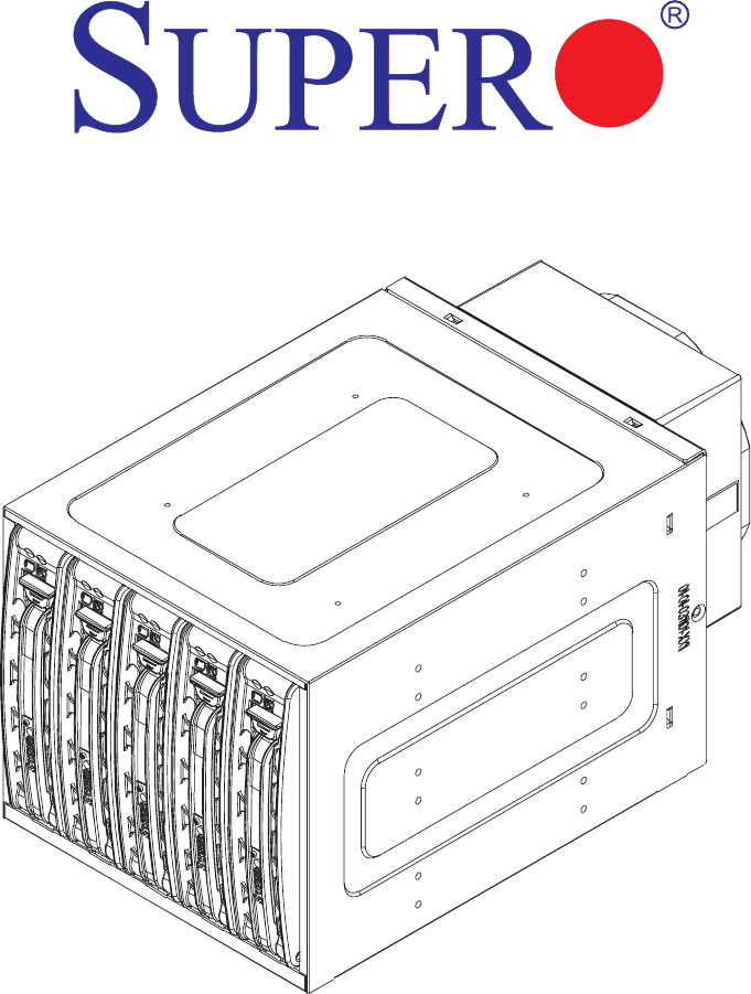
SAS M35TQ Mobile Rack User's Guide 3-3 Installation Procedures Use the following installation procedures to set up the Mobile Rack. For the SAS-M35TQ: ! 1. SAS IDs are assigned automatically by the backplane. Do not set ID's manually on the drives. 2. SAS termination is enabled by default on the SAS backplane. Mobile Rack Hard Drives The drives are mounted in drive carriers to simplify their installation and removal from the chassis. These carriers also help promote proper airflow for the drive bays.
Safety Information and Technical Specifications Dummy Drive Drive Tray Figure 3-2: Chassis Drive Tray ! Warning: Except for short periods of time (swapping hard drives), do not operate the server with the hard drives empty. The hard drive tray must have a hard drive or dummy drive installed. 1 1 Figure 3-3: Removing Dummy Drive from Tray To install a hard drive to the hard drive tray: 1. Remove the two screws holding connecting the drive tray the carrier. 2. Remove the tray from the carrier.
SAS M35TQ Mobile Rack User's Guide SAS/SATA or SCSI Hard Drive 4 4 Drive Tray Figure 3-4: Removing Hard Drive 3. Install a new drive into the carrier with the printed circuit board side facing down so that the mounting holes align with those in the carrier. 4. Secure the hard drive by tightening all six screws. 5. Replace the drive tray into the mobile rack. Make sure the close the drive tray handle. 6. Repeat these steps for each hard drive you want to install.
Safety Information and Technical Specifications Connecting Cables to the Mobile Rack Before connecting cables the mobile rack, you must remove the exhaust fan. In some circumstances, the backplane may need to be removed. Figure 3-5: Removing Mobile Rack Fan To connect SAS/SATA and power cables the mobile rack: 1. Before connecting the mobile rack, you must remove exhaust fan. To do this, pinch the tabs on each side of the unit (as illustrated).
SAS M35TQ Mobile Rack User's Guide Figure 3-6: Removing Mobile Rack Fan 2. Pull the exhaust fan from the chassis.
Safety Information and Technical Specifications Figure 3-7: Removing Mobile Rack Fan 3. Remove the bracket screw and pull the bracket from the mobile rack. 4. Connect the SAS cables and power cables to the mobile rack backplane. 5. Replace the bracket, bracket screw, and fan to the mobile rack.
SAS M35TQ Mobile Rack User's Guide Figure 3-8: Removing Mobile Rack Fan Additional Installation Information The backplane may be separated from the mobile rack by removing the seven screws holding the backplane in place.