
Ice Maker User Manual
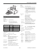


EPSON Stylus COLOR 500
EPSON Stylus COLOR 500 - 4 6/96 Ink Jet Printers
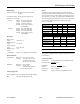
Pin assignments
Note:
■ The column heading “Direction” refers to the direction of signal
flow as viewed from the printer.
■ “Return Pin” denotes the twisted-pair return pin to be connected
at signal ground level. For the interface wiring, be sure to use a
twisted-pair cable for each signal and to complete the connection
on the return side.
■ All interface conditions are based on TTL level. Both the rise and
fall times of each signal must be less than 0.2 microseconds.
■ Data transfer must be carried out by observing the ACKNLG
or
BUSY signal. Data transfer to this printer can be carried out only
after receipt of the ACKNLG
signal or when the level of the BUSY
signal is LOW.
Reverse channel
Transmission
mode: IEEE-1284 Nibble mode
Adaptable
connector:
57-30360 (Amphenol) or equivalent
Synchronization: Refer to the IEEE-1284 specification
Handshaking: Refer to the IEEE-1284 specification
Signal level: IEEE-1284 level 1 device
Data
transmission
timing: Refer to the IEEE-1284 specification
Extensibility
request:
The printer responds to the extensibility
request in the affirmative when the request
is 00H or 04H, which means:
00H: Request nibble mode of reverse
channel transfer
04H: Request device ID in nibble mode of
reverse channel transfer
Signal
pin
Return
pin Signal Direction Description
1 19 STROBE
IN STROBE pulse to read data.
2
3
4
5
6
7
8
9
20
21
22
23
24
25
26
27
DATA 0
DATA 1
DATA 2
DATA 3
DATA 4
DATA 5
DATA 6
DATA 7
IN
IN
IN
IN
IN
IN
IN
IN
These signals represent
information in bits 0 to 7 of
parallel data respectively. Each
signal is at HIGH level when data
is logical 1 and LOW when it is
logical 0.
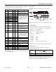
10 28 ACKNLG
OUT About a 5-
µ
s pulse. LOW
indicates data has been received
and the printer is ready to accept
more data.
11 29 BUSY OUT A HIGH signal indicates the
printer cannot receive data. The
signal goes HIGH in the following
cases:
1) During data entry (for each
character)
2) During initialization
3) During self test,
demonstration, and
default-setting printing
4) During a printer-error state
12 28 PE OUT A HIGH signal indicates the
printer is in a paper-out state or
in an error state
13 28 SLCT OUT Always at high when printer is on
14 30 AUTO
FEED
XT
IN Not used
15 - NC - Not connected
16 - GND - Logic ground level
17 - CHASSIS
GND
- Printer's chassis ground, which
is connected to the logic ground
18 - Logic H OUT Pulled up to +5 V through 3.9 K
Ω
resistance
19–30 - GND - Twisted-pair return signal
ground level
31 30 INIT
IN When this signal goes LOW, the
printer controller is reset to its
state when the power is first
turned on and the print buffer is
cleared. This level is normally
HIGH; its pulse width must be
more than 50
µ
s at the receiving
terminal.
32 29 ERROR
OUT This signal level goes LOW
when the printer:
1) Is out of paper
2) Is in an error state
3) Has no ink cartridges installed
33 - GND - Same as for Pins 19-30
34 - NC - Not connected
35 - +5 V OUT Pulled up to +5 V through 3.3 K
Ω
resistance
36 30 SLIN IN Not used