
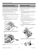
Ice Maker User Manual


EPSON Stylus COLOR 500
Ink Jet Printers 6/96 EPSON Stylus COLOR 500 - 5
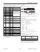
The following table lists the parallel connector pin assignments
and describes their respective interface signals.
Note:
The column heading “In/Out” refers to the direction of the signal flow
as viewed from the printer.
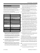
Timing chart
The figure below shows the timing chart for the parallel
interface.
Transition time (both the rise and the fall) of every signal must be less than
0.2
µ
s.
Serial Interface
The printer’s built-in serial interface is based on the RS-422
standard so you can connect the printer to an Apple Macintosh.
Standard: Based on RS-422
Synchronization: Asynchronous
Bit rate: 57.6 Kbps/230.4 Kbps
Handshaking: DTR protocol
Word format:
Data bit 8 bits
Parity bit None
Start bit 1 bit
Stop bit 1 bit
Connector: 8-pin mini-circular connector
Recommended
cable:
Apple System Peripheral-8 cable (M0197)
Initialization
The printer can be initialized (returned to a fixed set of
conditions) in these ways:
Each initialization method resets the font according to the
default settings selected using the control panel. However,
ESC @ does not initialize the printer mechanism, clear the input
data buffer, or clear the user-defined character set.
Pin
no. Signal name GND In/Out Description
1 HostClk 19 In Strobe pulse. Input data is latched
at falling edge of the signal.
2 DATA 1 20 In Bit 0: LSB Parallel input data to the
printer.
3 DATA 2 21 In These signals represent information
in bits 0 to 7 of parallel data
respectively. Each signal is at HIGH
level when data is logical 1 and LOW
when it is logical 0. These signals
are used to transfer the 1284
extensibility request values to the
printer.
4 DATA 3 22 In
5 DATA 4 23 In
6 DATA 5 24 In
7 DATA 6 25 In
8 DATA 7 26 In
9 DATA 8 27 In
10 PtrClk 28 Out Used to qualify data being sent to
the host. Set LOW then HIGH to
cause an interrupt indicating to host
that data is available.
11 PtrBusy/
DataBit-3,7
29 Out Data bits 3 then 7 indicate forward
channel busy status.
12 ACkDataReq/
DataBit-2,6
28 Out Data bits 2 then 6. Set HIGH until
host requests data transfer, then
follows
n
Data Avail (
n
Fault).
13 Xflag/
DataBit-1,5
28 Out X-flag signal and reverse channel
transfer data bit 1 then 5.
14 HostBusy 30 In Set LOW to indicate that host can
receive peripheral device to host
data. Then set high to acknowledge
receipt of that nibble. Set high in
response to PtrClk (
n
Ack) low pulse
to re-enter reverse data transfer
phase.
31 INIT 30 In Not used
32 DataAvail./
DataBit-0,4
29 Out This signal is LOW when the printer
is in an error state
36 1284-Active 30 In 1284 active signal
18 Logic H - Out Pulled up to +5V through 3.9 k
Ω
resistance.
35 +5V - Out Pulled up to +5V through 3.3 k
Ω
resistance.
17 Chassis - - Chassis GND
16,33,
19–30
GND - - Signal GND
15, 34 NC - - Not connected
Hardware
initialization
• The printer is turned on.
• The printer receives an INIT
signal
from the parallel interface: pin 31 goes LOW
Software
initialization
• Software sends the ESC @ (initialize the printer)
command; the last panel settings are kept
BUSY
DATA
0.5 µs (Min.)
0 µs (Min.)
5 µs (Typ.)
0 µs (Min.)
ACKNLG
STROBE