
User`s manual

Chapter 1: Introduction
1-5
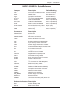
H8DCR-3/H8DCR-i Quick Reference
Jumpers Description Default Setting
J3P 3rd Power Fail Detect En/Dis Closed (Enabled)
JBT1 CMOS Clear See Section 2-7
JCF1 Compact Flash Select Closed (Master)
JI
2
C1/2 I
2
C to PCI Enable/Disable Closed (Enabled)
JPG1 VGA Enable/Disable Pins 1-2 (Enabled)
JPL1/JPL2 LAN1/2 Enable/Disable Pins 1-2 (Enabled)
JPS1 SAS Controller En/Disable Pins 1-2 (Enabled)
JPX1A/JPX2A PCI-X Slot #7/6 Freq. Select Open (Auto)
JD1 Internal Speaker En/Disable Pins 6-7 (Enabled)
JWD Watch Dog Pins 1-2 (Reset)
Connectors Description
COM1/COM2 Serial Ports
FAN 1-5 System Fan Headers
JIDE#1/JIDE#2 IDE Drive Connectors
J1B4 20-Pin ATX Power Connector
J22 System Management Bus Header
J32 4-pin Auxiliary Power Connector
JAR Power Supply Alarm Reset Header
JD1 Onboard Speaker/Keylock/Power LED
JF1 Front Panel Connector
JFDD1 Floppy Disk Drive Connector
JL1 Chassis Intrusion Header
LAN1/2 Gigabit Ethernet (RJ45) Ports
JOH1 Overheat Warning Header
JPW2 8-Pin Processor Power Connector
JPWF Power Fail Connector
JS4 I
2
C Connector for SAS Backplane
JSLED1 SAS Drive Activty LEDs
JSM1 /JSM2 SAS 4-7/SAS 0-3 Ports
JUSB2 Additional USB Headers (USB2/3)
JWF1 Compact Flash Power Connector
JWOL Wake-On-LAN Header
JWOR Wake-On-Ring Header
PS_SMBUS Power Supply I
2
C Header
SATA0-3 Serial ATA Ports
USB0/1 Universal Serial Bus (USB) Ports 0/1
Onboard Indicators Description
DP1 Power Standby LED
DS1-8 SAS Activity LEDs