SUPER H8DMR-82 H8DMR-i2 USER’S MANUAL Revision 1.
The information in this User’s Manual has been carefully reviewed and is believed to be accurate. The vendor assumes no responsibility for any inaccuracies that may be contained in this document, makes no commitment to update or to keep current the information in this manual, or to notify any person or organization of the updates. Please Note: For the most up-to-date version of this manual, please see our web site at www.supermicro.com. Super Micro Computer, Inc.
Preface Preface About This Manual This manual is written for system integrators, PC technicians and knowledgeable PC users. It provides information for the installation and use of the H8DMR-82/H8DMR-i2 serverboard. The H8DMR-82/H8DMR-i2 is based on the nVidia® MCP55 Pro/NEC uPD720400 chipset and supports single or dual AMD OpteronTM 2000 Series Socket F type processors and up to 64 GB of DDR2-667 /533/400 registered ECC SDRAM.
H8DMR-82/H8DMR-i2 User’s Manual Table of Contents Preface About This Manual ...................................................................................................... iii Manual Organization ................................................................................................... iii Chapter 1: Introduction 1-1 Overview ......................................................................................................... 1-1 Checklist .............................................
Table of Contents USB Ports .............................................................................................. 2-11 USB Headers ......................................................................................... 2-12 Serial Ports ............................................................................................. 2-12 Fan Headers .......................................................................................... 2-12 JLAN1/2 (Ethernet Ports) ...............................
H8DMR-82/H8DMR-i2 User’s Manual 2-10 Enabling SATA RAID .................................................................................... 2-24 2-11 Installing Additional Drivers .......................................................................... 2-26 Chapter 3: Troubleshooting 3-1 Troubleshooting Procedures ........................................................................... 3-1 Before Power On .....................................................................................
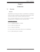
Chapter 1: Introduction Chapter 1 Introduction 1-1 Overview Checklist Congratulations on purchasing your computer serverboard from an acknowledged leader in the industry. Our boards are designed with the utmost attention to detail to provide you with the highest standards in quality and performance. Please check that the following items have all been included with your serverboard. If anything listed here is damaged or missing, contact your retailer.
H8DMR-82/H8DMR-i2 User’s Manual Contacting Supermicro Headquarters Address: Super Micro Computer, Inc. 980 Rock Ave. San Jose, CA 95131 U.S.A. Tel: +1 (408) 503-8000 Fax: +1 (408) 503-8008 Email: marketing@supermicro.com (General Information) support@supermicro.com (Technical Support) Web Site: www.supermicro.com Europe Address: Super Micro Computer B.V. Het Sterrenbeeld 28, 5215 ML 's-Hertogenbosch, The Netherlands Tel: +31 (0) 73-6400390 Fax: +31 (0) 73-6416525 Email: sales@supermicro.
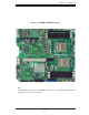
Chapter 1: Introduction Figure 1-1. H8DMR-82/H8DMR-i2 Image Note: The H8DMR-82 is pictured. The H8DMR-i2 shares the same layout but with no SCSI components, connectors or jumpers.
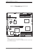
H8DMR-82/H8DMR-i2 User’s Manual Figure 1-2.
Chapter 1: Introduction H8DMR-82/H8DMR-i2 Quick Reference Jumpers Description Default Setting J3P 3rd Power Fail Detect En/Dis Closed (Enabled) JBT1 JCF1 JI2C1/2 CMOS Clear Compact Flash Master/Slave I2C to PCI Enable/Disable See Section 2-7 Closed (Master) Closed (Enabled) JPA1* SCSI Enable/Disable Pins 1-2 (Enabled) JPA2/JPA3* JPG1 SCSI Channel A/B Term. VGA Enable/Disable Open (Enabled) Pins 1-2 (Enabled) JPX1A PCI-X Slot #6 Freq. Select Open (Auto) JPX1B JWD PCI-X Slots #7 Freq.
H8DMR-82/H8DMR-i2 User’s Manual Serverboard Features CPU • Single or dual AMD Opteron 2000 Series Socket F type 64-bit processors Memory • Eight dual/single channel DIMM slots supporting up to 64 GB of DDR2-667 /533/400 registered ECC SDRAM Note: Memory capacities are halved for single CPU systems. Refer to Section 2-4 before installing.
Chapter 1: Introduction ACPI Features • Slow blinking LED for suspend state indicator • BIOS support for USB keyboard • Main switch override mechanism • Internal/external modem ring-on Onboard I/O • On-chip SATA controller supporting six (6) SATA ports (RAID 0, 1, 0+1 and 5) • Adaptec AIC-7902W SCSI controller (RAID 0, 1 and 10, H8DMR-82 only) • One (1) UltraDMA (ATA) 133/100 IDE port • One (1) floppy port interface (up to 2.
H8DMR-82/H8DMR-i2 User’s Manual DDR2-667/533/400 128-bit data + 16-bit ECC DIMM 1B DIMM 1A 128-bit data + 16-bit ECC AMD OpteronTM Processor (CPU2) DIMM 2B DIMM 2A DDR2-667/533/400 DIMM 2A DIMM 2B AMD OpteronTM Processor (CPU1) DIMM 1A DIMM 1B 16 x 16 HT link (1 GHz) PCI-X PCI-X 133 MHz Slot SATA Ports (6) CH B IDE (ATA133) PCI-X PCI-X 100 MHz Slot CH A NEC uPD720400 x8 PCI-E Bus MCP55 Pro USB Ports (4) ATI RN50 AIC 7902W GLAN Ports (2) PCI-E x8 Slot LPC SCSI Ports (2) PCI-E x8 Slo
Chapter 1: Introduction 1-2 Chipset Overview The H8DMR-82/H8DMR-i2 serverboard is based on the nVidia MCP55 Pro/NEC uPD720400 chipset. The nVidia MCP55 Pro functions as Media and Communications Processor (MCP) and the NEC chip as a PCI-X Tunnel. Controllers for the system memory are integrated directly into the AMD Opteron processors. MCP55 Pro Media and Communications Processor The MCP55 Pro is a single-chip, high-performance HyperTransport peripheral controller.
H8DMR-82/H8DMR-i2 User’s Manual 1-3 PC Health Monitoring This section describes the PC health monitoring features of the H8DMR-82/H8DMRi2. The serverboard has an onboard System Hardware Monitor chip that supports PC health monitoring. Onboard Voltage Monitors for two CPU cores, Hyper Transport (1.2V), memory banks (1.8V), chipset (1.5V) The onboard voltage monitor will scan these voltages continuously. Once a voltage becomes unstable, it will give a warning or send an error message to the screen.
Chapter 1: Introduction 1-4 Power Configuration Settings This section describes the features of your serverboard that deal with power and power settings. Slow Blinking LED for Suspend-State Indicator When the CPU goes into a suspend state, the chassis power LED will start blinking to indicate that the CPU is in suspend mode. When the user presses any key, the CPU will wake-up and the LED will automatically stop blinking and remain on.
H8DMR-82/H8DMR-i2 User’s Manual 1-5 Power Supply As with all computer products, a stable power source is necessary for proper and reliable operation. It is even more important for processors that have high CPU clock rates. The H8DMR-82/H8DMR-i2 accommodates 12V ATX power supplies. Although most power supplies generally meet the specifications required by the CPU, some are inadequate. A 2 amp current supply on a 5V Standby rail is strongly recommended.
Chapter 1: Introduction 1-6 Super I/O The disk drive adapter functions of the Super I/O chip include a floppy disk drive controller that is compatible with industry standard 82077/765, a data separator, write pre-compensation circuitry, decode logic, data rate selection, a clock generator, drive interface control logic and interrupt and DMA logic. The wide range of functions integrated onto the Super I/O greatly reduces the number of components required for interfacing with floppy disk drives.
H8DMR-82/H8DMR-i2 User’s Manual Notes 1-14
Chapter 2: Installation Chapter 2 Installation 2-1 Static-Sensitive Devices Electrostatic Discharge (ESD) can damage electronic components. To prevent damage to your system board, it is important to handle it very carefully. The following measures are generally sufficient to protect your equipment from ESD. Precautions • Use a grounded wrist strap designed to prevent static discharge. • Touch a grounded metal object before removing the board from the antistatic bag.
H8DMR-82/H8DMR-i2 User's Manual 2-2 Processor and Heatsink Installation Exercise extreme caution when handling and installing the proces- ! sor. Always connect the power cord last and always remove it before adding, removing or changing any hardware components. Installing the CPU Backplates Two CPU backplates (BKT-0011L) have been preinstalled to the serverboard to prevent the CPU area of the serverboard from bending and to provide a base for attaching the heatsink retention modules.
Chapter 2: Installation 3. Align pin 1 of the CPU with pin 1 of the socket. Once aligned, carefully place the CPU into the socket. Do not drop the CPU on the socket, move the CPU horizontally or vertically or rub the CPU against the socket or against any pins of the socket, which may damage the CPU and/or the socket. 4. With the CPU inserted into the socket, inspect the four corners of the CPU to make sure that it is properly installed and flush with the socket.
H8DMR-82/H8DMR-i2 User's Manual Installing the Heatsink Retention Modules Two heatsink retention modules (BKT-0012L) and four screws are included in the retail box. Once installed, these are used to help attach the heatsinks to the CPUs. To install, align the module with the standoffs of the preinstalled CPU backplate and with the four feet on the module contacting the serverboard. Secure the retention module to the backplate with two of the screws provided. See Figure 2-1.
Chapter 2: Installation 2-3 Mounting the Serverboard into a Chassis All serverboards and motherboards have standard mounting holes to fit different types of chassis. Make sure that the locations of all the mounting holes for both the serverboard and the chassis match. Although a chassis may have both plastic and metal mounting fasteners, metal ones are highly recommended because they ground the serverboard to the chassis. Make sure that the metal standoffs click in or are screwed in tightly. 1.
H8DMR-82/H8DMR-i2 User's Manual Support The H8DMR-82/H8DMR-i2 supports single or dual-channel, registered ECC DDR2667/533/400 SDRAM. Both interleaved and non-interleaved memory are supported, so you may populate any number of DIMM slots (see note on previous page and charts on following page). The CPU2 DIMM slots can only be accessed when two CPUs are installed (however, the CPU2 DIMM slots are not required to be populated when two CPUs are installed).
Chapter 2: Installation Populating Memory Banks for 128-bit Operation CPU1 DIMM1A CPU1 DIMM1B CPU1 DIMM2A CPU1 DIMM2B X X X X X X X X X X X X X X X X X X X X X X X X X X X X X X X X CPU2 DIMM1A CPU2 DIMM1B X X X X X X X X X X X X CPU2 DIMM2A CPU2 DIMM2B X X X X X X X X X X X X Notes: X indicates a populated DIMM slot.
H8DMR-82/H8DMR-i2 User's Manual 2-5 I/O Port and Control Panel Connections The I/O ports are color coded in conformance with the PC99 specification to make setting up your system easier. See Figure 2-3 below for the colors and locations of the various I/O ports. Figure 2-3. I/O Port Locations and Definitions Note: the external SCSI port is on the H8DMR-82 only. Front Control Panel JF1 contains header pins for various front control panel connectors.
Chapter 2: Installation 2-6 Connecting Cables ATX Power 20-pin Connector Pin Defintions (JPW1) ATX Power Connector Pin# Definition 11 +3.3V 1 +3.3V 12 -12V 2 +3.3V 13 COM 3 COM 14 PS_ON 4 +5V definitions of the ATX power connec- 15 COM 5 COM tor. This connection supplies power to 16 COM 6 +5V the chipset, fans and memory.
H8DMR-82/H8DMR-i2 User's Manual Power LED Power LED Pin Definitions (JF1) The Power LED connection is located Pin# Definition on pins 15 and 16 of JF1. Refer to the 15 Vcc table on the right for pin definitions. 16 Control HDD LED HDD LED Pin Definitions (JF1) The HDD (IDE Hard Disk Drive) LED connection is located on pins 13 and 14 of JF1. Attach the IDE hard drive LED cable to display disk activity. Refer to the table on the right for pin definitions.
Chapter 2: Installation Power Fail LED Power Fail LED Pin Definitions (JF1) The Power Fail LED connection is located on pins 5 and 6 of JF1. Refer to the table on the right for pin definitions. This feature is only available Pin# Definition 5 Vcc 6 Control for systems with redundant power supplies. Reset Button Reset Button Pin Definitions (JF1) The Reset Button connection is located on pins 3 and 4 of JF1. Attach it to the hardware reset switch on the computer case.
H8DMR-82/H8DMR-i2 User's Manual USB Headers Universal Serial Bus Headers Pin Definitions (USB2/3) Four additional USB2.0 headers (USB2/3) are included on the USB2 Pin # Definition USB3/4 Pin # Definition 1 +5V 1 +5V 2 PO- 2 PO- A USB cable (not included) is needed 3 PO+ 3 PO+ for the connection. See the table on 4 Ground 4 Ground the right for pin definitions. 5 Key 5 No connection serverboard. These may be connected to provide front side access.
Chapter 2: Installation Power LED/Speaker PWR LED Connector Pin Definitions (JD1) On JD1, pins 1, 2, and 3 are for the Pin# Definition power LED and pins 4 through 7 are 1 +Vcc for the speaker. See the tables on the right for pin definitions. 2 Control 3 Control Speaker Connector Pin Definitions (JD1) Note: The speaker connector pins are for use with an external speaker.
H8DMR-82/H8DMR-i2 User's Manual Wake-On-LAN Wake-On-LAN Pin Definitions (JWOL) The Wake-On-LAN header is designated JWOL. See the table on the Pin# Definition right for pin definitions. You must have a LAN card with a Wake-On-LAN 1 +5V Standby 2 Ground 3 Wake-up connector and cable to use the WakeOn-LAN feature. Note: Wake-On-LAN from S3, S4, S5 are supported by LAN1. LAN2 supports Wake-On-LAN from S1 only. Wake-On-Ring The Wake-On-Ring header is designated JWOR.
Chapter 2: Installation 3rd Power Supply Alarm Reset Header PS Alarm Reset Header Pin Definitions (JAR) Connect JAR to the alarm reset button on your chassis (if available) or to Pin# Definition 1 Ground 2 Reset Signal a microswitch to allow you to turn off the alarm that sounds when a power supply module fails. See the table on the right for pin definitions.
H8DMR-82/H8DMR-i2 User's Manual Power Fail Header Power Fail Header Pin Definitions (JPWF) Connect a cable from your power sup- Pin# Definition ply to the Power Fail header to provide 1 P/S 1 Fail Signal 2 P/S 2 Fail Signal 3 P/S 3 Fail Signal 4 Alarm Reset you with warning of a power supply failure. The warning signal is passed through the PWR_LED pin to indicate a power failure. See the table on the right for pin definitions.
Chapter 2: Installation CMOS Clear JBT1 is used to clear CMOS and will also clear any passwords. Instead of pins, this jumper consists of contact pads to prevent accidentally clearing the contents of CMOS. To clear CMOS, 1) First power down the system and unplug the power cord(s). 2) With the power disconnected, short the CMOS pads with a metal object such as a small screwdriver for at least four seconds. 3) Remove the screwdriver (or shorting device).
H8DMR-82/H8DMR-i2 User's Manual Watch Dog Watch Dog Jumper Settings (JWD) JWD controls Watch Dog, a system monitor that takes action when a soft- Jumper Setting Definition ware application freezes the system. Pins 1-2 Reset Jumping pins 1-2 will cause WD to Pins 2-3 NMI reset the system if an application is Open Disabled hung up. Jumping pins 2-3 will generate a non-maskable interrupt signal for the application that is hung up. See the table on the right for jumper settings.
Chapter 2: Installation Compact Flash Master/ Slave Compact Flash Master/Slave Jumper Settings (JCF1) The JCF1 jumper allows you to as- Jumper Setting sign either master or slave status to Closed Master Open Slave a compact flash card populating the JIDE1 slot . See the table on the right Definition for jumper settings. SCSI Controller Enable/ Disable (H8DMR-82 only) SCSI Enable/Disable Jumper Settings (JPA1) Jumper JPA1 is used to enable or disable the onboard SCSI controller.
H8DMR-82/H8DMR-i2 User's Manual 2-8 Onboard Indicators LAN1/LAN2 LEDs The Ethernet ports (located beside the VGA port) have two LEDs. LAN LED (Connection Speed Indicator) On each Gb LAN port, one LED indicates activity when blinking while the other LED may be amber or off to indicate the speed of the connection. LED Color Definition Amber 1 GHz Off 10/100 MHz See the table on the right for the functions associated with the connection speed LED.
Chapter 2: Installation 2-9 Floppy, IDE, SATA and SCSI Drive Connections Use the following information to connect the floppy and hard disk drive cables. The floppy disk drive cable has seven twisted wires. A red mark on a wire typically designates the location of pin 1. A single floppy disk drive ribbon cable has 34 wires and two connectors to provide for two floppy disk drives.
H8DMR-82/H8DMR-i2 User's Manual IDE Connector IDE Drive Connector Pin Definitions (JIDE1) There are no jumpers to config- Pin# Definition Pin # Definition ure the onboard JIDE1 connec- 1 Reset IDE 2 Ground tor. See the table on the right for pin definitions.
Chapter 2: Installation SCSI Connectors (H8DMR-82 only) Ultra320 SCSI Drive Connectors Pin Definitions (JA1, JB1) Refer to the table at right for pin definitions for the Ultra320 SCSI connectors located at JA1 and JB1.
H8DMR-82/H8DMR-i2 User's Manual 2-10 Enabling SATA RAID Now that the hardware is set up, you must now install the operating system and the SATA RAID drivers, if you wish to use RAID with your SATA drives. The installation procedure differs depending on whether you wish to have the operating system installed on a RAID array or on a separate non-RAID drive. See the instructions below for details.
Chapter 2: Installation 2. Use the arrow keys to move to Advanced > Floppy/IDE/SATA Configuration > nVidia RAID Setup and press the key. Once in the submenu, enable the "nVidia RAID Function" setting, which will cause the SATA0/1/2 Primary/Secondary settings to appear. Enable the SATA devices and channels you will be using. 3. Hit the key twice and scroll to the Exit menu. Select "Save Changes and Exit" and hit , then hit again to verify. 4.
H8DMR-82/H8DMR-i2 User's Manual 2-11 Installing Additional Drivers The CD that came bundled with the system contains software drivers, some of which must be installed, such as the chipset driver. After inserting this CD into your CDROM drive, the display shown in Figure 2-5 should appear. (If this display does not appear, click on the My Computer icon and then on the icon representing your CD-ROM drive. Finally, double click on the S "Setup" icon.) Figure 2-5.
Chapter 3: Troubleshooting Chapter 3 Troubleshooting 3-1 Troubleshooting Procedures Use the following procedures to troubleshoot your system. If you have followed all of the procedures below and still need assistance, refer to the ‘Technical Support Procedures’ and/or ‘Returning Merchandise for Service’ section(s) in this chapter. Always disconnect the AC power cord before adding, changing or installing any hardware components. Before Power On 1.
H8DMR-82/H8DMR-i2 User's Manual NOTE If you are a system integrator, VAR or OEM, a POST diagnostics card is recommended. For I/O port 80h codes, refer to App. B. Memory Errors 1. Make sure that the DIMM modules are properly and fully installed. 2. You should be using registered ECC DDR2 memory (see next page). Also, it is recommended that you use the same memory type and speed for all DIMMs in the system. See Section 2-4 for memory details and limitations. 3.
Chapter 3: Troubleshooting 3. If you still cannot resolve the problem, include the following information when contacting us for technical support: Serverboard model and PCB revision number BIOS release date/version (this can be seen on the initial display when your system first boots up) System configuration An example of a Technical Support form is posted on our web site. 4.
H8DMR-82/H8DMR-i2 User's Manual Question: Why can't I turn off the power using the momentary power on/off switch? Answer: The instant power off function is controlled in BIOS by the Power Button Mode setting. When the On/Off feature is enabled, the serverboard will have instant off capabilities as long as the BIOS has control of the system.
Chapter 4: BIOS Chapter 4 BIOS 4-1 Introduction This chapter describes the AMIBIOS™ Setup utility for the H8DMR-82/H8DMR-i2. The AMI ROM BIOS is stored in a flash chip and can be easily upgraded using a floppy disk-based program. Note: Due to periodic changes to the BIOS, some settings may have been added or deleted and might not yet be recorded in this manual. Please refer to the Manual Download area of our web site for any changes to BIOS that may not be reflected in this manual.
H8DMR-82/H8DMR-i2 User’s Manual 4-2 Main Menu When you first enter AMI BIOS Setup Utility, you will see the Main Menu screen. You can always return to the Main Menu by selecting the Main tab on the top of the screen with the arrow keys. The Main Menu screen provides you with a system overview, which includes the version, built date and ID of the AMIBIOS, the type, speed and number of the processors in the system and the amount of memory installed in the system.
Chapter 4: BIOS Advanced ACPI Configuration ACPI Version Features Use this setting the determine which ACPI version to use. Options are ACPI v1.0, ACPI v2.0 and ACPI v3.0. ACPI APIC Support Determines whether to include the ACPI APIC table pointer in the RSDT pointer list. The available options are Enabled and Disabled. ACPI OEMB Table Determines whether to include the ACPI APIC table pointer in the RSDT pointer list. The available options are Enabled and Disabled.
H8DMR-82/H8DMR-i2 User’s Manual Floppy/IDE/SATA Configuration Onboard Floppy Controller Use this setting to Enable or Disable the onboard floppy controller. Floppy A Move the cursor to these fields via up and down keys to select the floppy type. The options are Disabled, 360 KB 5 1/4", 1.2 MB 5 1/4", 720 KB 3½", 1.44 MB 3½”, and 2.88 MB 3½". Onboard IDE Controller There is a single floppy controller on the motherboard, which may be Enabled or Disabled with this setting.
Chapter 4: BIOS Primary IDE Master/Slave Highlight one of the items above and press to access the submenu for that item. Type Select the type of device connected to the system. The options are Not Installed, Auto, CDROM and ARMD. LBA/Large Mode LBA (Logical Block Addressing) is a method of addressing data on a disk drive. The options are Disabled and Auto. Block (Multi-Sector Transfer) Block mode boosts IDE drive performance by increasing the amount of data transferred.
H8DMR-82/H8DMR-i2 User’s Manual DMA Mode Selects the DMA Mode. Options are SWDMA0, SWDMA1, SWDMA2, MWDMA0. MDWDMA1, MWDMA2, UDMA0. UDMA1, UDMA2, UDMA3, UDMA4 and UDMA5. (SWDMA=Single Word DMA, MWDMA=Multi Word DMA, UDMA=UltraDMA.) S.M.A.R.T. Self-Monitoring Analysis and Reporting Technology (SMART) can help predict impending drive failures. Select "Auto" to allow BIOS to auto detect hard disk drive support. Select "Disabled" to prevent AMI BIOS from using the S.M.A.R.T.
Chapter 4: BIOS PIO Mode PIO (Programmable I/O) mode programs timing cycles between the IDE drive and the programmable IDE controller. As the PIO mode increases, the cycle time decreases. The options are Auto, 0, 1, 2, 3, and 4. Select Auto to allow AMI BIOS to auto detect the PIO mode. Use this value if the IDE disk drive support cannot be determined. Select 0 to allow AMI BIOS to use PIO mode 0. It has a data transfer rate of 3.3 MBs. Select 1 to allow AMI BIOS to use PIO mode 1.
H8DMR-82/H8DMR-i2 User’s Manual PCI/PnP Configuration Load Onboard LAN Option ROM Use this setting to Enable or Disable the onboard option ROM. Clear NVRAM Select Yes to clear NVRAM during boot-up. The options are Yes and No. Plug & Play OS Select Yes to allow the OS to configure Plug & Play devices. (This is not required for system boot if your system has an OS that supports Plug & Play.) Select No to allow AMIBIOS to configure all devices in the system.
Chapter 4: BIOS Advanced Chipset Control NorthBridge Configuration Memory Configuration Memclock Mode This setting determines how the memory clock is set. Auto has the memory clock by code and Limit allows the user to set a standard value. MCT Timing Mode Sets the timing mode for memory. Options are Auto and Manual. Bank Interleaving Select Auto to automatically enable interleaving-memory scheme when this function is supported by the processor. The options are Auto and Disabled.
H8DMR-82/H8DMR-i2 User’s Manual DRAM Scrub Redirect Allows system to correct DRAM ECC errors immediately, even with background scrubbing on. Options are Enabled and Disabled. DRAM BG Scrub Corrects memory errors so later reads are correct. Options are Disabled and various times in nanoseconds and microseconds. L2 Cache BG Scrub Allows L2 cache RAM to be corrected when idle. Options are Disabled and various times in nanoseconds and microseconds.
Chapter 4: BIOS MAC1 LAN1 Settings are Auto and Disabled for MAC1 LAN1. MAC1 LAN1 Bridge Settings are Enabled and Disabled for MAC1 LAN1 bridge. Legacy USB Support Select "Enabled" to enable the support for USB Legacy. Disable Legacy support if there are no USB devices installed in the system. "Auto" disabled Legacy support if no USB devices are connected. The options are Disabled, Enabled and Auto.
H8DMR-82/H8DMR-i2 User’s Manual Serial Port 2 Mode Tells BIOS which mode to select for serial port 2. The options are Normal, IrDA and ASKIR. DMI Event Logging View Event Log Highlight this item and press to view the contents of the event log. Mark All Events as Read Highlight this item and press to mark all events as read. Clear Event Log Select Yes and press to clear all event logs. The options are Yes and No to verify.
Chapter 4: BIOS Options are Disable (no redirection after BIOS POST), Boot Loader (redirection during POST and during boot loader) and Always (redirection always active). Note that some OS's may not work with this set to Always. Terminal Type Selects the type of the target terminal. Options are ANSI, VT100 and VT- UTF8. VT-UTF8 Combo Key Support Allows you to Enable or Disable VT-UTF8 combination key support for ANSI/ VT100 terminals.
H8DMR-82/H8DMR-i2 User’s Manual FAN1 Speed through FAN5 Speed The speeds of the onboard fans (in rpm) are displayed here. FAN1 Speed Down Time Use the "+" and "-" keys to set the fan speed time interval of the ramp down. FAN1 Speed Up Time Use the "+" and "-" keys to set the fan speed time interval of the ramp up. Tolerance for Fan Control Set the fan control tolerance. Options are Disabled, 6ºC, 7ºC, 8ºC, 9ºC and 10ºC. Level1 Temperature Set the reference point to transfer to the next fan speed.
Chapter 4: BIOS IPMI Configuration View BMC System Event Log Pressing the Enter key will open the following settings. Use the "+" and "-" keys to navigate through the system event log. Clear BMC System Event Log Selecting this and pressing the Enter key will clear the BMC system event log. Set LAN Configuration Use the "+" and "-" keys to choose the desired channel number. IP Address Use the "+" and "-" keys to select the parameter. The IP address and current IP address in the BMC are shown.
H8DMR-82/H8DMR-i2 User’s Manual Startup Delay Use this setting to Enable or Disable the startup delay. Event Message for PEF Action Use this setting to Enable or Disable event messages for a PEF action. BMC Watch Dog Timer Action This setting is used to set the Watch Dog function. The options are Disabled, Reset System, Power Down and Power Cycle.
Chapter 4: BIOS CD/DVD Drives This feature allows the user to specify the Boot sequence from available CD/DVD drives. OS Installation Change this setting if using a 64-bit Linux operating system. The available options are Other and 64-bit Linux 2.6.9. 4-5 Security Menu AMI BIOS provides a Supervisor and a User password. If you use both passwords, the Supervisor password must be set first.
H8DMR-82/H8DMR-i2 User’s Manual 4-6 Exit Menu Select the Exit tab from AMI BIOS Setup Utility screen to enter the Exit BIOS Setup screen. Save Changes and Exit When you have completed the system configuration changes, select this option to leave BIOS Setup and reboot the computer, so the new system configuration parameters can take effect. Select Save Changes and Exit from the Exit menu and press .
Appendix A: BIOS Error Beep Codes Appendix A BIOS Error Beep Codes During the POST (Power-On Self-Test) routines, which are performed each time the system is powered on, errors may occur. Non-fatal errors are those which, in most cases, allow the system to continue the boot-up process. The error messages normally appear on the screen. Fatal errors are those which will not allow the system to continue the boot-up procedure.
H8DMR-82/H8DMR-i2 User’s Manual Notes A-2
Appendix B: BIOS POST Checkpoint Codes Appendix B BIOS POST Checkpoint Codes When AMIBIOS performs the Power On Self Test, it writes checkpoint codes to I/O port 0080h. If the computer cannot complete the boot process, diagnostic equipment can be attached to the computer to read I/O port 0080h. B-1 Uncompressed Initialization Codes The uncompressed initialization checkpoint codes are listed in order of execution: Checkpoint Code Description D0h The NMI is disabled. Power on delay is starting.
H8DMR-82/H8DMR-i2 User’s Manual B-2 Bootblock Recovery Codes The bootblock recovery checkpoint codes are listed in order of execution: Checkpoint Code Description E0h The onboard floppy controller if available is initialized. Next, beginning the base 512 KB memory test. E1h Initializing the interrupt vector table next. E2h Initializing the DMA and Interrupt controllers next. E6h Enabling the floppy drive controller and Timer IRQs. Enabling internal cache memory.
Appendix B: BIOS POST Checkpoint Codes B-3 Uncompressed Initialization Codes The following runtime checkpoint codes are listed in order of execution. These codes are uncompressed in F0000h shadow RAM. Checkpoint Code Description 03h The NMI is disabled. Next, checking for a soft reset or a power on condition. 05h The BIOS stack has been built. Next, disabling cache memory. 06h Uncompressing the POST code next. 07h Next, initializing the CPU and the CPU data area.
H8DMR-82/H8DMR-i2 User’s Manual Checkpoint Code Description 25h Interrupt vector initialization is done. Clearing the password if the POST DIAG switch is on. 27h Any initialization before setting video mode will be done next. 28h Initialization before setting the video mode is complete. Configuring the monochrome mode and color mode settings next. 2Ah Bus initialization system, static, output devices will be done next, if present. See the last page for additional information.
Appendix B: BIOS POST Checkpoint Codes Checkpoint Code Description 4Ch The memory below 1 MB has been cleared via a soft reset. Clearing the memory above 1 MB next. 4Dh The memory above 1 MB has been cleared via a soft reset. Saving the memory size next. Going to checkpoint 52h next. 4Eh The memory test started, but not as the result of a soft reset. Displaying the first 64 KB memory size next. 4Fh The memory size display has started. The display is updated during the memory test.
H8DMR-82/H8DMR-i2 User’s Manual Checkpoint Code Description 86h The password was checked. Performing any required programming before WINBIOS Setup next. 87h The programming before WINBIOS Setup has completed. Uncompressing the WINBIOS Setup code and executing the AMIBIOS Setup or WINBIOS Setup utility next. 88h Returned from WINBIOS Setup and cleared the screen. Performing any necessary programming after WINBIOS Setup next. 89h The programming after WINBIOS Setup has completed.
Appendix B: BIOS POST Checkpoint Codes Checkpoint Code Description A9h Returned from adaptor ROM at E000h control. Performing any initialization required after the E000 option ROM had control next. Aah Initialization after E000 option ROM control has completed. Displaying the system configuration next. Abh Uncompressing the DMI data and executing DMI POST initialization next. B0h The system configuration is displayed. B1h Copying any code to specific areas.
H8DMR-82/H8DMR-i2 User’s Manual (continued from front) The products sold by Supermicro are not intended for and will not be used in life support systems, medical equipment, nuclear facilities or systems, aircraft, aircraft devices, aircraft/emergency communication devices or other critical systems whose failure to perform be reasonably expected to result in significant injury or loss of life or catastrophic property damage.