
User`s manual

Chapter 2: Installation
2-17
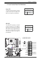
JL1
JI2C1
JI2C2
JOH
JPUSB1
JPI1
JWD
JPL1
JPAC
JLED
JPD1
COM1
JPW1
Floopy
JPW2
JWOL
DIMM1
DIMM2
CD1
SPKR1
LE1
JD1
Fan5
Fan4
Fan1
Fan3
Fan2
LAN1
JPUSB2
DIMM2B
DIMM4
DIMM3
USB 10/11
USB 8/9
USB6
1394_2
Slot7 PCI-E x1
Slot6 PCI-E Gen2 x16
Slot3 PCI 33MHz
HD AUDIO
JWOR
CPU
CPU Fan
FP Audio
1394_1
CMOS CLEAR
C2SEA/C2SEE
IDE
VGA
HDMI
USB/0/1
I-SATA3
I-SATA2
I-SATA1
I-SATA0
Slot1 PCI 33MHz
Slot5 PCI 33MHZ
Slot4 PCI-E x4 on x16
KB/Mouse
SPI BIOS
Slot2 PCI 33MHz
DIMM2A
DIMM1B
DIMM1A
USB7
JF1
USB2/3/4/5
SPDIF_Out
Printer
I-SATA4
I-SATA5
Battery
Intel
G45 (C2SEA)
G43 (C2SEE)
ICH10
Intel
Lan
CTRL
S I/O
IDE
CTRL
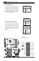
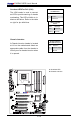
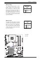
Fan Headers
The C2SEA/C2SEE has ve chassis fan
headers (Fan 1 to Fan 5). Fan 1 is the
CPU Fan. Fan 2 to Fan 5 are system/
chassis fans.
Note: Pins 1-3 of a 4-pin fan headers
are backward compatible with the tra-
ditional 3-pin fans. See the table on the
right for pin denitions. The onboard
fan speeds are controlled by Thermal
Management via BIOS Hardware
Monitoring in the Advanced Setting.
(Note: Default: Disabled. When using
Thermal Management settings, please
use all 3-pin fans or all 4-pin fans on
the motherboard.)
A. Fan 1 (CPU Fan)
B. Fan 2
C. Fan 3
D. Fan 4
E. Fan 5
F. VGA
Fan Header
PinDenitions(Fan1-3)
Pin# Denition
1 Ground
2 +12V
3 Tachometer
4 PWR Modulation
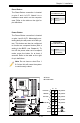
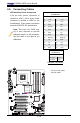
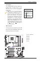
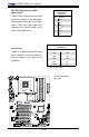
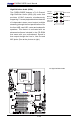
VGA Connector
A VGA connector is located next to the USB
ports 2~5 on the IO backplane. Refer to the
board layout below for the location.
A
B
C
D
E
F