
User`s manual
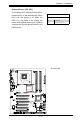


Chapter 2: Installation
2-31
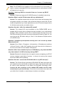
JL1
JI2C1
JI2C2
JOH
JPUSB1
JPI1
JWD
JPL1
JPAC
JLED
JPD1
COM1
JPW1
Floopy
JPW2
JWOL
DIMM1
DIMM2
CD1
SPKR1
LE1
JD1
Fan5
Fan4
Fan1
Fan3
Fan2
LAN1
JPUSB2
DIMM2B
DIMM4
DIMM3
USB 10/11
USB 8/9
USB6
1394_2
Slot7 PCI-E x1
Slot6 PCI-E Gen2 x16
Slot3 PCI 33MHz
HD AUDIO
JWOR
CPU
CPU Fan
FP Audio
1394_1
CMOS CLEAR
C2SEA/C2SEE
IDE
VGA
HDMI
USB/0/1
I-SATA3
I-SATA2
I-SATA1
I-SATA0
Slot1 PCI 33MHz
Slot5 PCI 33MHZ
Slot4 PCI-E x4 on x16
KB/Mouse
SPI BIOS
Slot2 PCI 33MHz
DIMM2A
DIMM1B
DIMM1A
USB7
JF1
USB2/3/4/5
SPDIF_Out
Printer
I-SATA4
I-SATA5
Battery
Intel
G45 (C2SEA)
G43 (C2SEE)
ICH10
Intel
Lan
CTRL
S I/O
IDE
CTRL
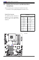
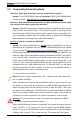
A. Power LED
Onboard PWR LED Indicator (LE1)
LED Color Denition
Off System Off
On Standby Power On
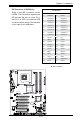
Onboard Power LED (LE1)
The Onboard 3.3V Standby Power LED is
located at LE1 on the motherboard. When
LE1 is off, the system is off. When the
LED is on, the power is on. Unplug the
power cable before removing or installing
components. See the layout below for the
LED location.
A