C7SIM-Q USER’S MANUAL Revision 1.
The information in this User’s Manual has been carefully reviewed and is believed to be accurate. The vendor assumes no responsibility for any inaccuracies that may be contained in this document, makes no commitment to update or to keep current the information in this manual, or to notify any person or organization of the updates. Please Note: For the most up-to-date version of this manual, please see our web site at www.supermicro.com. Super Micro Computer, Inc.
Preface Preface This manual is written for system integrators, PC technicians and knowledgable PC users. It provides information for the installation and use of the C7SIM-Q motherboard. The C7SIM-Q supports a single Intel® CoreTM i7, Core i5, Core i3 and Pentium® processor series in an LGA1156 socket. Featuring the Intel Q57 Express, the C7SIM-Q also offers substantial enhancement in price/system performance ratio in a cost-effective, small form-factor package. Please refer to our web site (http://www.
C7SIM-Q User’s Manual Table of Contents Preface ......................................................................................................................... iii Manual Organization ..................................................................................................... iii Conventions Used in the Manual................................................................................... iii Quick-Start Guide............................................................................
Table of Contents ATX/Auxiliary Power Connectors ............................................................ 2-20 Universal Serial Bus (USB)...................................................................... 2-21 Chassis Intrusion....................................................................................... 2-21 Fan Headers.............................................................................................. 2-22 ATX PS/2 Keyboard and PS/2 Mouse Ports....................................
C7SIM-Q User’s Manual No Video ................................................................................................... 3-1 Memory Errors............................................................................................ 3-2 Losing the System’s Setup Configuration . ............................................... 3-2 3-2 Technical Support Procedures ........................................................................ 3-2 3-3 Frequently Asked Questions .............................
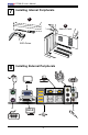
Quick-Start Guide Installing the Processor 1 3 1 4 2 2 Installing the Heatsink and Fans 1 3 4 2 vii
C7SIM-Q User’s Manual 3 Installing the Memory Modules 1 2 Press Down Lock 3 Lock 4 Installing the I/O Shield 1 2 Note: The chassis image included here is for illustration purposes only.
5 Installing the Motherboard 1 2 3 JPUSB2 4 6 Connecting the Power Supply JPUSB2 JPUSB2 2 1 ix
C7SIM-Q User’s Manual 7 Installing Internal Peripherals 1 2 Add-on Cards SATA Drives 8 Installing External Peripherals DVI-D x
Chapter 1: Introduction Chapter 1 Introduction 1-1 Overview Checklist Congratulations on purchasing your computer motherboard from an acknowledged leader in the industry. Supermicro boards are designed with the utmost attention to detail to provide you with the highest standards in quality and performance. Please check that the following items have all been included with your motherboard. If anything listed here is damaged or missing, contact your retailer.
C7SIM-Q User’s Manual Contacting Supermicro Headquarters Address: Tel: Fax: Email: Web Site: Super Micro Computer, Inc. 980 Rock Ave. San Jose, CA 95131 U.S.A. +1 (408) 503-8000 +1 (408) 503-8008 marketing@supermicro.com (General Information) support@supermicro.com (Technical Support) www.supermicro.com Europe Address: Tel: Fax: Email: Super Micro Computer B.V.
Chapter 1: Introduction C7SIM-Q Image Note: All pictures and drawings shown in this manual were based upon the latest PCB Revision available at the time of publishing of the manual. The motherboard you've received may or may not look exactly the same as the one shown in this manual.
C7SIM-Q User’s Manual Motherboard Layout 43 1 42 1 11 12 13 15 16 19 41 1 44 1 14 40 1 17 18 39 1 38 1 10 1 37 1 111 12 1 45 1 13 1 47 1 14 1 26 1 48 1 15 1 36 1 34 1 46 1 35 1 32 1 33 1 27 1 31 1 30 1 49 1 16 1 JPUSB2 17 1 18 1 19 1 20 1 21 1 23 1 22 1 24 1 25 1 28 1 Important Notes to the User • Jumpers not indicated are for test purposes only. • See Chapter 2 for detailed information on jumpers, I/O ports and JF1 front panel connections.
Chapter 1: Introduction C7SIM-Q Quick Reference Number Connectors Description 40 19,20 JPW1 COM1, COM2 44 12,35,36,43 DIMM 1A, 2A, 1B, 2B Fans 4,2,1,3 ATX 24-Pin Power Connector Serial Port 1 & 2 Headers Memory Slots 29 37 33 38 2 21 23 32 3 17 1 42 11 6 9 39 28 45 47 48 49 5 7 10 22,24 31 41 25 15 T-SGPIO-0/1 JF1 JL1 JLED VGA JWOL JWOR SPK DVI J5 J8 JPW2 J6 LAN1 LAN2 LED2 SATA 0,1,2,3,4,5 JPCIE4 JPCIE3 JPCIE2 JPCIE1 USB 0, 1, 2, 3 USB 4/5 USB 6/7 USB 8, 9 USB 10/11, 12/13 JPI2C BATT JS/PDIF
C7SIM-Q User’s Manual Number 27 16 14 Jumpers JBT1 JI2C1/JI2C2 JPAC Description CMOS Clear SMB to PCI Slots Audio Enable USB Wake-up Enable (JPUSB1: Back Panel, JPUSB2: Front Panel) 4, 46 JPUSB1, JPUSB2 30 JD1 External Buzzer/Speaker 8 13 JPL1 JPL2 LAN1 Enable/Disable LAN2 Enable/Disable 26 JPT1 Trusted Platform Module Enable 34 JP3 18 JL2 Intel Management Engine AC97/HD Audio Selector (Front Panel) 1-6 Default Setting (See Chapter 2) Open/Open (Disabled) Pins 1-2 (Enabled) Pins 1-2 (Ena
Chapter 1: Introduction Motherboard Features CPU Single Intel® CoreTM i7, Core i5, Core i3 and Pentium® series processor in an LGA1156 socket. Memory Four (4) 240-pin, DDR3 SDRAM DIMM sockets with support for up to 16GB of UDIMM memory (Non-ECC/DDR3 1333/1066/800 MHz memory only.) DIMM sizes UDIMM 1GB, 2GB, and 4GB Chipset Intel Q57 Express Chipset Expansion Slots One (1) PCI-Express 2.0 x16 One (1) PCI-Express 2.0 x4 (in x16 slot) One (1) PCI-Express 2.
C7SIM-Q User’s Manual Plug and Play (PnP), APM 1.2, PCI 2.3, ACPI 1.0/2.0, USB Keyboard Support PC Health Monitor- Onboard voltage monitors for CPU core voltage, memory ing voltage, +1.8V, +3.3V, +5 +/-12V, +3.3V standby, +5V standby, Vbat (battery voltage), HT, Memory, Chipset.
Chapter 1: Introduction Block Diagram PCIe x16 SLOT PCIe2.0_x16 5.0Gb VID[0-7] Intel LGA1156 Processor 6 SATA PORTS 14 USB PORTS CK505 Rev1.0 FLASH SPI 64Mb DIMM1(Far) DIMM2 4 UDIMM 2.5Gb PCIe_5~8_x4 2.5Gbps Intel Q57 PCH SATA-II 300MB/s USB2.0 PCIe x1 SLOT PCIe_2_x1 2.5Gbps GLAN2 82574L RJ45 ALC889 HD 7.1 PCIe_1_x1 2.5Gbps HD 480Mbps PCIe x16 SLOT PCIe_3_x1 2.
C7SIM-Q User’s Manual 1-2 Chipset Overview The C7SIM-Q supports the Intel® CoreTM i7, Core i5, Core i3 and Pentium® processor series for the LGA 1156 socket. Built upon the functionality and the capability of the single-chip Intel Q57 Express chipset, the C7SIM-Q motherboard provides the performance and feature set required for single-processor-based systems with configuration options optimized for Small Office/Home Office (SOHO) computing platforms.
Chapter 1: Introduction 1-3 PC Health Monitoring This section describes the PC health monitoring features of the C7SIM-Q. These features are supported by an onboard System Hardware Monitor chip. Recovery from AC Power Loss BIOS provides a setting for you to determine how the system will respond when AC power is lost and then restored to the system.
C7SIM-Q User’s Manual Slow Blinking LED for Suspend-State Indicator When the CPU goes into a suspend state, the chassis power LED will start blinking to indicate that the CPU is in the suspend mode. When the user presses any key, the CPU will wake-up and the LED indicator will automatically stop blinking and remain on. BIOS Support for USB Keyboard If the USB keyboard is the only keyboard in the system, it will function as a normal keyboard during system bootup.
Chapter 1: Introduction 1-6 Super I/O The C7SIM-Q provides two onboard high-speed, 16550-compatible (UART) serial communication headers. Each UART includes a 16-byte send/receive FIFO, a programmable baud rate generator, complete modem control capability and a processor interrupt system. Both UARTs provide legacy speed with baud rate of up to 115.2 Kbps as well as an advanced speed with baud rates of 250 K, 500 K, or 1 Mb/s, which support higher speed modems.
C7SIM-Q User’s Manual configuration technology for AMT that enable a user to configure “bare-bones” systems before the OS and/or software management agents are installed. Intel Trusted Execution Technology (Intel TXT) Intel Trusted Execution Technology (Intel TXT) is used to verify a launch environment. It establishes the root of trust, which allows software to establish a chain of trust for virtualized environments.
Chapter 2: Installation Chapter 2 Installation 2-1 Electro-Static Sensitive Devices Electro-static Discharge (ESD) can damage electronic components. To prevent damage to your system board, it is important to handle it very carefully. The following measures are generally sufficient to protect your equipment from ESD. Precautions • Use a grounded wrist strap designed to prevent static discharge. • Touch a grounded metal object before removing the board from the antistatic bag.
C7SIM-Q User's Manual 2-2 Motherboard Installation All motherboards have standard mounting holes to fit different types of chassis. Make sure that the locations of all the mounting holes for both motherboard and chassis match. Although a chassis may have both plastic and metal mounting fasteners, metal ones are highly recommended because they ground the motherboard to the chassis. Make sure that the metal standoffs click in or are screwed in tightly.
Chapter 2: Installation Installation Instructions 1 Install the I/O shield into the chassis. I/O Shield 2 3 Locate the mounting holes on the motherboard. Refer to the layout on the previous page for mounting hole locations. Locate the matching mounting holes on the chassis. Install standoffs in the chassis as needed. Align the mounting holes on the motherboard against the mounting holes on the chassis.
C7SIM-Q User's Manual 2-3 ! Processor and Heatsink Installation Warning: When handling the processor package, avoid placing direct pressure on the label area of fan. Notes: Always connect the power cord last and always remove it before adding, removing or changing any hardware components. Make sure that you install the processor into the CPU socket before you install the CPU heatsink. If you buy a CPU separately, make sure that you use an Intel-certified multi-directional heatsink only.
Chapter 2: Installation 2 Gently lift the load lever to open the load plate. Remove the plastic cap. 3 Use your thumb and your index finger to hold the CPU at the top center edge and the bottom center edge of the CPU. 4 Align the CPU key that is the semi-circle cutouts against the socket keys. Once the CPU key is aligned, carefully lower the CPU straight down to the socket (Do not drop the CPU on the socket. Do not move the CPU horizontally or vertically).
C7SIM-Q User's Manual the socket, inspect the four corners of the CPU to make sure that the CPU is properly installed. 5 Use your thumb to gently push the load lever down to the lever lock. CPU properly installed Load lever locked into place Warning: The CPU will only seat inside the socket in one direction. Make sure it is properly inserted before closing the load plate. If it doesn't close properly, do not force it as it may damage your CPU.
Chapter 2: Installation Installing a Passive CPU Heatsink 1 2 3 4 Do not apply any thermal grease to the heatsink or the CPU die for the required amount has already been applied. Place the heatsink on top of the CPU so that the four mounting holes are aligned with those on the Motherboard and the Heatsink Bracket underneath. Screw in two diagonal screws (i.e., the #1 and the #2 screws) until just snug (do not over-tighten the screws to avoid possible damage to the CPU.
C7SIM-Q User's Manual Removing the Heatsink ! 1 2 3 4 Warning: We do not recommend that the CPU or the heatsink be removed. However, if you do need to uninstall the heatsink, please follow the instructions below to uninstall the heatsink to prevent damage done to the CPU or the CPU socket. Unscrew the heatsink screws from the motherboard in the sequence as shown in the illustration below. Gently wriggle the heatsink to loosen it from the CPU.
Chapter 2: Installation Installing an Active Fan CPU Heatsink 1 Locate the CPU Fan power connector on the motherboard. 2 Position the heatsink so that the heatsink fan wires are closest to the CPU fan power connector and are not interfered with other components. 3 Inspect the CPU Fan wires to make sure that the wires are routed through the bottom of the heatsink. 4 Remove the thin layer of the protective film from the copper core of the heatsink.
C7SIM-Q User's Manual 7 Align the four heatsink fasteners with the mounting holes on the motherboard. Gently push the pairs of diagonal fasteners (#1 & #2, and #3 & #4) into the mounting holes until you hear a click. (Note: Make sure to orient each fastener so that the narrow end of the groove is pointing outward.) 8 Repeat Step 7 to insert all four heatsink fasteners into the mounting holes.
Chapter 2: Installation Removing the Heatsink Warning: We do not recommend that the CPU or the heatsink be removed. However, if you do need to remove the heatsink, please follow the instructions below to uninstall the heatsink and prevent damage to the CPU or other components. Active Heatsink Removal 1 Unplug the power cord from the power supply. 2 Disconnect the heatsink fan wires from the CPU fan header.
C7SIM-Q User's Manual 2-4 System Memory CAUTION Exercise extreme care when installing or removing DIMM modules to prevent any possible damage. Note: Check the Supermicro website for a list of memory modules that have been validated with the C7SIM-Q motherboard. How to Install DIMMs 1. Insert the desired number of DIMMs into the memory slots, starting with DIMM1A (Channel 1, DIMMA - see the Figure below), then DIMM2A, DIMM1B & DIMM2B. Insert each DIMM module vertically into its slot.
Chapter 2: Installation Installing and Removing DIMMs 1 Position the bottom key of the DIMM module so it aligns with the receptive point on the slot. Notches 2 Push the Lock/Release tabs to their Release positions. Make sure that the notches on a DIMM module align with the Lock/Release tabs on the memory slot as it is pressed in. 3 Insert the DIMM module vertically and press down until the module snaps into place.
C7SIM-Q User's Manual Note: Due to memory allocation to system devices, the amount of memory that remains available for operational use will be reduced when 4 GB of RAM is used. The reduction in memory availability is disproportional. For Microsoft Windows users: Microsoft implemented a design change in Windows XP with Service Pack 2 (SP2) and Windows Vista. This change is specific to the Physical Address Extension (PAE) mode behavior which improves driver compatibility.
Chapter 2: Installation 2-5 Control Panel Connectors/IO Ports The I/O ports are color coded in conformance with the PC 99 specification. See Figure below for the colors and locations of the various I/O ports. 1. Back Panel Connectors/IO Ports JPUSB2 8 2 4 7 17 20 13 16 19 12 15 18 11 14 6 10 5 9 Rear View 1 3 Back Panel I/O Port Locations and Definitions Back Panel Connectors 1. Keyboard (Purple) 11. LAN 1 Port 2. PS/2 Mouse (Green) 12. USB Port 6 3. DVI-D Port 13.
C7SIM-Q User's Manual 2. Front Control Panel JF1 contains header pins for various buttons and indicators that are normally located on a control panel at the front of the chassis. These connectors are designed specifically for use with Super Micro server chassis. See Figure below for the descriptions of the various control panel buttons and LED indicators. Refer to the following section for descriptions and pin definitions.
Chapter 2: Installation 3. Front Control Panel Pin Definitions Power LED The Power LED connection is located on pins 15 and 16 of JF1. Refer to the table on the right for pin definitions. Power LED Pin Definitions (JF1) Pin# Definition 15 LED_Anode+ 16 PWR LED Signal HDD LED The HDD LED connection is located on pins 13 and 14 of JF1. Attach a hard drive LED cable here to display disk activity (for any hard drives on the system, including SAS and Serial ATA).
C7SIM-Q User's Manual NIC1/NIC2 Indicator GLAN 1 LED Pin Definitions (JF1) The NIC1 and NIC2 (Network Interface Controller) LED connection for the GLAN ports are located on pins 11 & 12, and 9 & 10 of JF1. Attach the NIC LED cables to display network activity. Refer to the table on the right for pin definitions.
Chapter 2: Installation Reset Button The Reset Button connection is located on pins 3 and 4 of JF1. Attach it to a hardware reset switch on the computer case. Refer to the table on the right for pin definitions. Reset Button Pin Definitions (JF1) Pin# Definition 3 Reset 4 Ground Power Button The Power Button connection is located on pins 1 and 2 of JF1. Momentarily contacting both pins will power on/off the system.
C7SIM-Q User's Manual 2-6 Connecting Cables ATX/Auxiliary Power Connectors ATX Power 24-pin Connector Pin Definitions A 24-pin main power connector is located at JPW1. This power connector meets the SSI EPS 12V specification. See the table on the right for pin definitions. 8-Pin Auxiliary Power Connector In addition to the ATX main power, the 8-pin 12V power connector located at JPW2 is also required to provide power to the South Bridge, North Bridge and all VRMs.
Chapter 2: Installation Universal Serial Bus (USB) Front Panel USB (10/11/12/13) and FrontAccessible Onboard USB (8/9) Connections There are 14 USB 2.0 (Universal Serial Bus) ports/headers on the motherboard. Eight (8) of them are back panel USB ports (USB 0/1/2/3, USB 4/5 and USB 6/7). There are also four (4) headers that can be used for front panel connections (USB 10/11, USB 12/13), and two (2) vertical "Type A" USB ports (USB 8 and USB 9). See the tables on the right for pin definitions.
C7SIM-Q User's Manual Fan Headers The C7SIM-Q has four chassis fan headers (Fan 1 to Fan 4). Fan 4 is the CPU Fan. Fan 1 to Fan 3 are system/chassis fans. Note: Pins 1-3 of a 4-pin fan headers are backward compatible with the traditional 3-pin fans.) See the table on the right for pin definitions. *The onboard fan speeds are controlled by Thermal Management via BIOS Hardware Monitoring in the Advanced Setting. (Default: Disabled.
Chapter 2: Installation ATX PS/2 Keyboard and PS/2 Mouse Ports PS/2 Keyboard and Mouse Port Pin Definitions The ATX PS/2 keyboard and the PS/2 mouse ports are located at J8. The mouse port is above the keyboard port. See the table on the right for pin definitions. Serial Ports COM1 and COM2 are serial port headers. See the table on the right for pin definitions.
C7SIM-Q User's Manual Wake-On-Ring The Wake-On-Ring header is designated JWOR. This function allows your computer to "wake-up" when receiving an incoming call when in the suspend state. See the table on the right for pin definitions. You must have a Wake-On-Ring card and cable to use this feature. Wake-On-Ring Pin Definitions (JWOR) Pin# Definition 1 Ground 2 Wake-up Wake-On-LAN The Wake-On-LAN header is located at JWOL on the motherboard. See the table on the right for pin definitions.
Chapter 2: Installation LAN 1 and LAN 2 (Gigabit Ethernet Ports) Two (2) built-in 100/1000 LAN ports are located on the I/O backpanel. These ports accept RJ45 type cables. LAN1 / LAN2 Speaker A Speaker/Buzzer header is located on the motherboard. See the table on the right for speaker pin definitions. Note: The speaker connector pins are for use with an external speaker. If you wish to use the onboard speaker, you should close pins 3-4 with a jumper.
C7SIM-Q User's Manual High Definition Audio (HDA) The C7SIM-Q features a 7.1+2 Channel High Definition Audio (HDA) codec that provides 10 DAC channels, simultaneously supporting 7.1 sound playback and two channels of independent stereo sound output (multiple streaming) through the front panel stereo out for front L&R, rear L&R, center and subwoofer speakers. This feature is activated with the Advanced software in the CD-ROM that came with your motherboard.
Chapter 2: Installation Front Panel Audio Control If supplied with our chassis, attach the Front Panel audio interface card to this header. Note that if front panel headphones are plugged in, the back panel audio output is disabled. In addition, if the front panel interface card is not connected to the front panel audio header, jumpers should be installed on the header pin pairs: 1-2, 5-6, and 9-10.
C7SIM-Q User's Manual VGA Port A VGA port is located next to the Keyboard/ Mouse port on the back panel. Refer to the board layout for the location. DVI-D Port The DVI-D port (Digital Visual Interface) is a multi-pin interface designed for carrying high-resolution video signals. The DVI Port is located below the VGA Connector on the I/O backpanel. Refer to the board layout below for the location. This connector is used to display high definition video for monitors that support DVI signals.
Chapter 2: Installation T-SGPIO 0/1 Headers Two T-SGPIO (Serial-Link General Purpose Input/Output) headers are located near the SATA connectors on the motherboard. These headers are used to communicate with the enclosure management chip in the system. See the table on the right for pin definitions. Refer to the board layout below for the locations of the headers.
C7SIM-Q User's Manual 2-7 Jumper Settings Explanation of Jumpers To modify the operation of the motherboard, jumpers can be used to choose between optional settings. Jumpers create shorts between two pins to change the function of the connector. Pin 1 is identified with a square solder pad on the printed circuit board. See the motherboard layout pages for jumper locations. Note: On two pin jumpers, "Closed" means the jumper is on and "Open" means the jumper is off the pins.
Chapter 2: Installation Audio Enable Audio Enable (JPAC) JPAC enables or disables the onboard audio connections. See the table on the right for jumper settings. The default setting is Enabled. Pin# Definition 1-2 Enabled (*default) 2-3 Disabled HD Audio / AC97 Audio HD/AC97 Select JL2 allows selection between High Definition Audio output or legacy AC97 audio. see the table on the right for jumper settings. The default setting is HD Audio.
C7SIM-Q User's Manual Speaker On the JD1 header, Pins 3~4 are used for internal speaker. Close Pins 3~4 with a cap to use the onboard speaker. If you wish to use an external speaker, close Pins 1~4 with a cable. See the table on the right for pin definitions. Speaker Connector Pin Definitions Pin Setting Definition Pins 3~4 Internal Speaker Pins1~4 External Speaker LAN Port Enable/Disable GLAN Enable Jumper Settings Use JPL1/JPL2 to enable or disable LAN Port 1 and LAN Port 2 on the motherboard.
Chapter 2: Installation TPM Support Enable TPM Support Enable Jumper Settings JPT1 allows the user to enable TPM Jumper Setting (Trusted Platform Modules) support to enhance data integrity and system security. See the table on the right for jumper settings. The default setting is disabled. 1-2 Enabled 2-3 Disabled Definition A. TPM enable A B. Clear CMOS B Clear CMOS JBT1 is used to clear CMOS. Instead of pins, this "jumper" consists of contact pads to prevent the accidental clearing of CMOS.
C7SIM-Q User's Manual USB Wake-Up Use the JPUSB jumpers to enable the function of "System Wake-Up via USB devices", which allows you to "wake-up" the system by pressing a key on the USB or PS/2 keyboard or by clicking the USB or PS/2 mouse of your system. The JPUSB jumpers are used together with the USB Wake-Up function in the BIOS. Enable both the jumpers and the BIOS setting to allow the system to "wake-up via USB Devices". See the table on the right for jumper settings and jumper connections.
Chapter 2: Installation 2-8 Onboard Indicators GLAN Activity LED Indicator GLAN LEDs There are two Gigabit-LAN ports. Each of these Gigabit Ethernet LAN ports has two LEDs. The yellow LED (right) indicates activity, while the Link/Speed LED (left) may be green, amber or off to indicate the speed of the connection. See the tables at right for more information.
C7SIM-Q User's Manual Onboard Power LED (LED2) The Onboard 3.3V Standby Power LED is located at LED2 on the motherboard. When LED2 is off, the system is off. When the LED light is green, the system is on. When the LED is on, the Standby Power is on. Unplug the power cable before removing or installing components. See the layout below for the LED location. Onboard PWR LED Indicator (LE1) LED Color Definition Off System Off On Standby Power On Green System On A.
Chapter 2: Installation 2-9 Disk Drive Connections SATA Disk Drive Connectors SATA Connectors Pin Definitions Six Serial ATA (SATA) disk drive connectors (I-SATA 0~5) are located on the motherboard. See the table on the right for pin definitions.
C7SIM-Q User's Manual Notes 2-38
Chapter 3: Troubleshooting Chapter 3 Troubleshooting 3-1 Troubleshooting Procedures Use the following procedures to troubleshoot your system. If you have followed all of the procedures below and still need assistance, refer to the ‘Technical Support Procedures’ and/or ‘Returning Merchandise for Service’ section(s) in this chapter. Always disconnect the AC power cord before adding, changing or installing any hardware components. Before Power On 1.
C7SIM-Q User's Manual 2. Use the speaker to determine if any beep codes exist. Refer to Appendix A for details on beep codes. Note: If you are a system integrator, VAR or OEM, a POST diagnostics card is recommended. For I/O port 80h codes, refer to App. B. Memory Errors 1. Make sure that the DIMM modules are properly installed. 2. You should be using unbuffered DDR2 memory (see the next page). Also, it is recommended that you use the same memory speed for all DIMMs in the system.
Chapter 3: Troubleshooting 3. If you still cannot resolve the problem, include the following information when contacting Super Micro for technical support: • Motherboard model and PCB revision number • BIOS release date/version (this can be seen on the initial display when your system first boots up) • System configuration An example of a Technical Support form is on our web site at (http://www. supermicro.com/support/contact.cfm). 4.
C7SIM-Q User's Manual Notes: Be sure to type in a space after "ami". The drive letter "F:\>" is used only as an example and is the drive letter of your bootable device or USB pen/ thumb drive. It may be different on your system. Always use the file named “ami.bat” to update the BIOS. When completed, your system will automatically reboot. If you choose the .exe file, please run the .exe file under Windows to create the BIOS flash floppy disk. Insert the floppy disk into the system you wish to flash the BIOS.
Chapter 3: Troubleshooting Question: I installed my microphone correctly but I can't record any sound. What should I do? Answer: Go to , , , and then . Under the Properties tab, scroll down the list of devices in the menu and check the box beside "Microphone". Question: After I have installed 4 pieces of 1GB Memory, why does the BIOS only detect about 3.
C7SIM-Q User's Manual Notes 3-6
Chapter 4: AMI BIOS Chapter 4 BIOS 4-1 Introduction This chapter describes the AMI BIOS Setup Utility for the C7SIM-Q. The AMI ROM BIOS is stored in a Flash EEPROM and can be easily updated. This chapter describes the basic navigation of the AMI BIOS Setup Utility setup screens. Note: For instructions on BIOS recovery, please refer to the instruction guide posted at http://www.supermicro.com/support/manuals/.
C7SIM-Q How to Start the Setup Utility Normally, the only visible Power-On Self-Test (POST) routine is the memory test. As the memory is being tested, press the key to enter the main menu of the AMI BIOS Setup Utility. From the main menu, you can access the other setup screens. An AMI BIOS identification string is displayed at the left bottom corner of the screen, below the copyright message. Warning! Do not upgrade the BIOS unless your system has a BIOS-related issue.
Chapter 4: AMI BIOS System Overview: The following BIOS information will be displayed: System Time/System Date Use this option to change the system time and date. Highlight System Time or System Date using the arrow keys. Enter new values through the keyboard. Press the key or the arrow keys to move between fields. The date must be entered in Day MM/DD/YY format. The time is entered in HH:MM:SS format. (Note: The time is in the 24-hour format. For example, 5:30 P.M. appears as 17:30:00.
C7SIM-Q 4-3 Advanced Setup Configurations Use the arrow keys to select Boot Setup and hit to access the submenu items: BIOS SETUP UTILTY Main Advanced Security Boot Exit Advanced Settings Configure Settings during System Boot.
Chapter 4: AMI BIOS Wait For 'F1' If Error This forces the system to wait until the 'F1' key is pressed if an error occurs. The options are Disabled and Enabled. Unsupported CPU/Memory Check This feature displays a warning message when an unsupported CPU or memory is installed. The options are Enabled and Disabled. Hit 'Del' Message Display This feature displays "Press DEL to run Setup" during POST. The options are Enabled and Disabled.
C7SIM-Q Resume on RTC Alarm This feature enables or disables the RTC to generate a wake event. The options are Enabled and Disabled. If this is set to Enabled, the following appears: RTC Alarm Date (Days) - select using the [-] or [+] keys to select from Every Day through 1-31. RTC Alarm Time [HH:MM:SS] - Use [ENTER], [TAB] or [SHIFT-TAB] to select a field. Use the [+] or [-] keys to select. Processor & Clock Options Warning: Take Caution when changing the Advanced settings.
Chapter 4: AMI BIOS Intel® Virtualization Technology (Available when supported by the CPU) Select Enabled to use the feature of Virtualization Technology to allow one platform to run multiple operating systems and applications in independent partitions, creating multiple "virtual" systems in one physical computer. The options are Enabled and Disabled. Note: If there is any change to this setting, you will need to power off and restart the system for the change to take effect.
C7SIM-Q Intel® C-STATE Tech If enabled, C-State is set by the system automatically to either C2, C3 or C4 state. The options are Default and Enabled. C-State package limit setting If set to Auto, the AMI BIOS will automatically set the limit on the C-State package register. The options are Auto, C1, C3, C6 and C7. C1 Auto Demotion When enabled, the CPU will conditionally demote C3, C6 or C7 requests to C1 based on un-core auto-demote information. The options are Disabled and Enabled.
Chapter 4: AMI BIOS providing the user with greater reliability, security and availability in networking and data-sharing. The settings are Enabled and Disabled. Active State Power Management Select Enabled to start Active-State Power Management for signal transactions between L0 and L1 Links on the PCI Express Bus. This maximizes power-saving and transaction speed. The options are Enabled and Disabled. Route Port 80h Cycles to This feature allows the user to decide which bus to send debug information to.
C7SIM-Q IDE Detect Timeout (sec) Use this feature to set the time-out value for the BIOS to detect the ATA, ATAPI devices installed in the system. The options are 0 (sec), 5, 10, 15, 20, 25, 30, and 35. SATA 0 ~ 5 These settings allow the user to set the parameters of the disc storage devices attached to the SATA ports. Press to activate the following submenu screen for detailed options of these items. Set the correct configurations accordingly.
Chapter 4: AMI BIOS Select 2 to allow the AMI BIOS to use PIO mode 2. It has a data transfer rate of 8.3 MBs. Select 3 to allow the AMI BIOS to use PIO mode 3. It has a data transfer rate of 11.1 MBs. Select 4 to allow the AMI BIOS to use PIO mode 4. It has a data transfer bandwidth of 32-Bits. Select Enabled to enable 32-Bit data transfer. DMA Mode Select Auto to allow the BIOS to automatically detect IDE DMA mode when the IDE disk drive support cannot be determined.
C7SIM-Q tect hard disk drive support. Select Disabled to prevent the AMI BIOS from using the S.M.A.R.T. Select Enabled to allow the AMI BIOS to use the S.M.A.R.T. to support hard drive disk. The options are Disabled, Enabled, and Auto. 32-Bit Data Transfer Select Enable to enable the function of 32-bit IDE data transfer. The options are Enabled and Disabled.
Chapter 4: AMI BIOS Load Onboard LAN1 Option ROM/Load Onboard LAN2 Option ROM This feature is to enable or disable the onboard option ROMs. The options are Disabled and Enabled. Boot Graphics Adapter Priority Use the feature to select the graphics controller to be used as the primary boot device. The options are Onboard VGA and Other.
C7SIM-Q Redirection After BIOS POST Select Disabled to turn off Console Redirection after Power-On Self-Test (POST). Select Always to keep Console Redirection active all the time after POST. (Note: This setting may not be supported by some operating systems.) Select Boot Loader to keep Console Redirection active during POST and Boot Loader. The options are Disabled, Boot Loader, and Always. Terminal Type This feature allows the user to select the target terminal type for Console Redirection.
Chapter 4: AMI BIOS and system cooling. In both the alarms above, please take immediate action as shown below. CPU Temperature The CPU Temperature feature will display the CPU temperature status as detected by the BIOS: Low – This level is considered as the ‘normal’ operating state. The CPU temperature is well below the CPU ‘Temperature Tolerance’. The motherboard fans and CPU will run normally as configured in the BIOS (Fan Speed Control). User intervention: No action required.
C7SIM-Q ‘Temperature Threshold’ or ‘Temperature Tolerance’ has been assigned at the factory and is the baseline by which the motherboard takes action during different CPU temperature conditions (i.e., by increasing CPU Fan speed, triggering the Overheat Alarm, etc). Since CPUs can have different ‘Temperature Tolerances’, the installed CPU can now send its ‘Temperature Tolerance’ to the motherboard resulting in better CPU thermal management.
Chapter 4: AMI BIOS ACPI Configuration Use this section to configure the Advanced Configuration and Power Interface (ACPI) power management settings for your system.
C7SIM-Q APIC ACPI SCI IRQ When this item is set to Enabled, APIC ACPI SCI IRQ is supported by the system. The options are Enabled and Disabled. Headless Mode This feature is used to enable the system to function without a keyboard, monitor or mouse attached The options are Enabled and Disabled. ACPI Version Features The options are ACPI v1.0, ACPI v2.0 and ACPI v3.0. Please refer to ACPI's website for further explanation: http://www.acpi.
Chapter 4: AMI BIOS Clear event log This option clears the Event Log memory of all messages. The options are OK and Cancel. PCIE Error Log Use this option to enable logging of errors encountered in the system's PCIe bus. The options are Yes and No. ME Subsystem Configuration BootBlock HECI Message Enable this option to allow Boot Block HECI messaging between the systemBIOS and the ME firmware. The options are Disabled and Enabled. HECI Message This feature enables or disables the HECI message.
C7SIM-Q ME Firmware Image ReFlash Enable this option to allow the reflashing of the ME firmware. The options are Disabled and Enabled. Intel® AMT Configuration Intel AMT Support This option enables Intel AMT support. The options are Enabled and Disabled. Force IDER This option enables IDE Redirection. The options are Disabled, IDER Pri. Master, IDER Pri. Slave, IDER Sec. Master and IDER Sec. Slave. Force SOL This option enables Serial Over LAN (SOL) redirection. The options are Disabled, and Enabled.
Chapter 4: AMI BIOS 4-4 Security Settings The AMI BIOS provides a Supervisor and a User password. If you use both passwords, the Supervisor password must be set first. BIOS SETUP UTILTY Main Advanced Security Boot Exit Security Settings Install or Change the password.
C7SIM-Q Clear User Password (Available only if User Password has been set) Password Check Available options are Setup and Always. Boot Sector Virus Protection When Enabled, the AMI BOIS displays a warning when any program (or virus) issues a Disk Format command or attempts to write to the boot sector of the hard disk drive. The options are Enabled and Disabled. 4-5 Boot Settings BIOS SETUP UTILTY Main Advanced Security Boot Exit Boot Settings Specifies the Boot Device Priority sequence.
Chapter 4: AMI BIOS Hard Disk Drives This feature allows the user to specify the sequence of priority from the available Hard Drives. • 1st Drive [SATA: XXXXXXXXXX] • 2nd Drive [SATA: XXXXXXXXXX] Removable Drives This feature allows the user to specify the boot sequence from available Removable Drives. The settings are 1st boot device, 2nd boot device, and Disabled.
C7SIM-Q Save Changes and Exit When you have completed the system configuration changes, select this option to leave the BIOS Setup Utility and reboot the computer, so the new system configuration parameters can take effect. Select Save Changes and Exit from the Exit menu and press . Discard Changes and Exit Select this option to quit the BIOS Setup without making any permanent changes to the system configuration, and reboot the computer.
Appendix A: AMIBIOS Error Beep Codes Appendix A BIOS Error Beep Codes During the POST (Power-On Self-Test) routines, which are performed each time the system is powered on, errors may occur. Non-fatal errors are those which, in most cases, allow the system to continue the boot-up process. The error messages normally appear on the screen. Fatal errors are those which will not allow the system to continue the boot-up procedure.
C7SIM-Q User’s Manual Notes
Appendix B: Software Installation Instructions Appendix B Software Installation Instructions A. Installing Drivers After you've installed the Windows Operating System, a screen as shown below will appear. You are ready to install software programs and drivers that have not yet been installed. To install these software programs and drivers, click the icons to the right of these items. (Note: To install the Windows Operating System, please refer to the instructions posted on our website at http://www.
C7SIM-Q User's Manual B. Configuring Supero Doctor III The Supero Doctor III program is a Web-based management tool that supports remote management capability. It includes Remote and Local Management tools. The local management is called the SD III Client. The Supero Doctor III program included on the CDROM that came with your motherboard allows you to monitor the environment and operations of your system.
Appendix B: Software Installation Instructions Supero Doctor III Interface Display Screen-II (Remote Control) Note: SD III Software Revision 1.0 can be downloaded from our Web site at: ftp://ftp.supermicro.com/utility/Supero_Doctor_III/. You can also download SDIII User's Guide at: http://www.supermicro.com/PRODUCT/Manuals/SDIII/UserGuide.pdf. For Linux, we will still recommend that you use Supero Doctor II.
C7SIM-Q User's Manual Notes B-4
Intel® AMT Management Engine Setup Appendix C Intel® AMT Management Engine Setup This section describes how to setup the Intel Active Management Technology (AMT) Engine using the Intel Management Engine BIOS Extension.
C7SIM-Q User's Manual Setup 1. Immediately after POST, press to enter the AMT configuration. Intel (R) Management Engine BIOS Extension v6.0.3.019 Copyright (C) 2003-09 Intel Corporation. All Rights Reserved. Intel (R) ME Firmware versioin 6.0.4.0.1215 Press to enter Remote Assistance Press to enter Intel (R) ME Setup 2. To log into the Intel Management Engine (ME), enter the password. If this is your first login, the default password is "admin".
Intel® AMT Management Engine Setup If you see the following message: "Error - Intel(R) ME password change rejected", then you are using a weak password. Please enter a different password. 3. Select "Intel® ME General Settings" at the MAIN MENU. Intel (R) Management Engine BIOS Extension v6.0.3.019/Intel (R) ME Firmware versioin 6.0.4.0.1215 Copyright (C) 2003-09 Intel Corporation. All Rights Reserved.
C7SIM-Q User's Manual Intel® ME Platform Configuration Intel (R) Management Engine BIOS Extension v6.0.3.019/Intel (R) ME Firmware versioin 6.0.4.0.1215 Copyright (C) 2003-09 Intel Corporation. All Rights Reserved.
Intel® AMT Management Engine Setup Network Setup Intel® ME Network Name Settings • Host Name - This will be the host name of the machine. • Domain Name - A domain name where the machine belongs to. • Shared/Dedicated FQDN - This determines if the FQDN (Fully Qualified Domain Name) is shared with the host and the same as the operating system machine or is unique to the Intel ME.
C7SIM-Q User's Manual Manual ID - The IPv6 Interface ID is set manually. Selecting this type requires that the Manual Interface ID is set with a valid value. • IPV6 Address - Enter the IPV6 address. • IPV6 Default Router - Enter the IPV6 address of the network router this interface will use. • Preferred DNS IPV6 Address - the DNS server your network uses. • Alternate DNS IPV6 Address - a secondary DNS server your network uses.
Appendix E: BIOS Recovery Appendix D - BIOS Recovery The recovery procedure described in this section is to be used only when you are advised by your Supermicro Technical Support representative, or in cases of emergencies where the system no longer can boot due to a corrupted BIOS. DO NOT re-program (re-flash) the BIOS if your system is running properly.
C7SIM-Q User's Manual 5. When the Boot Sector Recovery Process is complete, the system will reboot automatically and you will see a checksum error on your screen. Part 2 - BIOS Reprogramming (Re-Flashing) After completing the Boot Sector Recovery Process, you will need to reprogram (“re-flash”) the proper BIOS binary file again into the BIOS ROM in order to have the correct BIOS file loaded by the system.
(Disclaimer) The products sold by Supermicro are not intended for and will not be used in life support systems, medical equipment, nuclear facilities or systems, aircraft, aircraft devices, aircraft/emergency communication devices or other critical systems whose failure to perform be reasonably expected to result in significant injury or loss of life or catastrophic property damage.