
User`s manual


Chapter 2: Installation
2-17
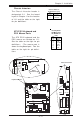
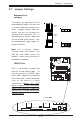
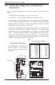
Front Side Bus Speeds
JP1, JP2 are used to set the sys-
tem (front side) bus speed for the
processors. It is best to keep this
jumper set to Auto. This jumper is
used together with the CPU Clock
setting in BIOS. See the table on
the right for jumper settings.
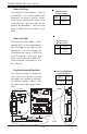
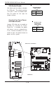
Jumper
Position
Pins 1-2
Pins 2-3
Open
Definition
WD to Reset
WD to NMI
Disabled
Watch Dog
Jumper Settings (JP8)
JP1 JP2
Auto 1-2 1-2
100 MHz (x4) 2-3 2-3
133 MHz (x4) NC 2-3
Reserved NC NC
200 MHz (x4) 2-3 NC
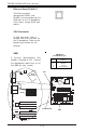
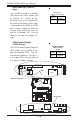
CPU
478 PGA
MCH
CPU FAN
COM2
USB 1/2
Parallel Port
KB/Mouse WakeUp
WOR
O
H
F
A
N
COM 1
VGA
GLAN 1
PCI 1-X
PCI-X 2
PCI 2
SCSI Channel A
BATTERY
BIOS
DIMM 0A
DIMM 0B
DIMM 1B
Watch Dog
FRONT PANEL CTR
BANK0
BANK1
Hance
Rapids
®
JF1
I
R
Super I/O
Ext Speaker
SATA LED
Keylock
JBTL1
24-pin ATX
Conn
S
U
P
E
R
P
4
S
C
8
GLAN 2
PCI 1
DIMM 1A
CHS FAN2
ID
E
2
K
B
/
M
o
u
s
e
USBWakeUp
Cha Instr.
LAN2 Enable
+12V PWR
PWR Froce On
(North Bridge)
CHS FAN4
CHS FAN3
CPU SPeeds
SATA1
Clear CMOS
USB3/4
VGA Enable
GLAN CTLR
GLAN CTLR
OH Fan Force-On
External SCSI-B
SCSI
VGA
SCSI 1-2 Enable
ID
E
1
WOL
PWR LED
CHS FAN1
CPU FAN
SATA2
F
l
o
p
p
y
SMBus
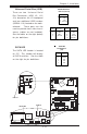
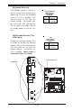
CPU
478 PGAMCH
CPU FAN
COM2
USB 1/2
rallel Port
KB/Mouse WakeUp
WOR
COM 1
Watch Dog
FRONT PANEL CTR
JF1
S
u
p
e
r I/O
24-pin ATX
Conn
KB/
Mouse
USBWakeUp
+12V PWR
PWR Froce On
(North Bridge)
CPU SPeeds
GLAN CTLR
PWR LED
CHS FAN1
CPU FAN
Watch Dog Enable
CPU Speeds
Watch Dog Enable/Disable
JP8 enables the control of the
Watch Dog function. Watch Dog
is a system monitor that can
reboot the system when a soft-
ware application is "hung up".
Pins 1-2 will cause WD to reset
the system if an applicantion is
"hung up". Pins 2-3 will generate
a non-maskable interrupt for the
application that is "hung up". See
the table on the right for jumper
settings. Watch Dog can also be
enabled via BIOS. (*Note, when
enabled, the user needs to write
his own application software in
order to disable the Watch Dog
Timer.)