
User`s manual

Chapter 2: Installation
2-23
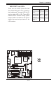
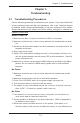
PCI 32-bit 33 MHz
S
A+/PDSMA-E+MSDP REPU
®
CPU
LGA 775
KB/MS
COM1
JLAN1
North Bridge
JPL1
JL1
JLE D
24-Pin ATX PWR
ICH7R
South Bridge
8-pin PWR
Battery
J 9
LRTC PF
USB 1/2
VGA
JLAN2
LAN1
CTRL
S I/O
Printer
JPL2
Floppy
DIMM 2B
PCI-X 64-bit 133 MHz
BI OS
PXH-V
Primary IDE
JWOR
LE1
JBT1
USB3/4
USB5/6
JP3
JPF
JWD
WOL
Fa n3
DIMM 1B
DIMM 2A
DIMM 1A
VG A
CTRL
LE3
LE4
*Compact Flash only
COM2
PCI 32-bit 33 MHz
JI2C1
JI2C2
JPG1
LAN2
CTRL
IPMI 2.0
SATA0
SATA1
SATA2
SATA3
Fan1
Fan4
Fa n6
Fan2
Fan5
PCI 32-bit 33 MHz
PCI 32-bit 33 MHz
PCI 32-bit 33 MHz
JWF1
SPKR
PCI-Exp. x8
Intel 3000
JPR1
PW3
PW4
(CPUFan)
Intel 3010
OR
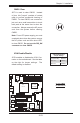
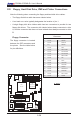
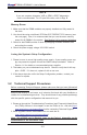
CMOS Clear
JBT1 is used to clear CMOS. Instead
of pins, this "jumper" consists of contact
pads to prevent accidental clearing of
CMOS. To clear CMOS, use a metal ob-
ject such as a small screwdriver to touch
both pads at the same time to short the
connection. Always remove the AC power
cord from the system before clearing
CMOS.
Note: For an ATX power supply, you must
completely shut down the system, remove
the AC power cord and then short JBT1
to clear CMOS. Do not use the PW_ON
connector to clear CMOS.
A
B
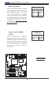
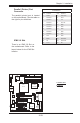
A. Clear CMOS
B. VGA Enabled
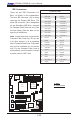
VGA Enable/Disable
JPG1 enables or disables the VGA Con-
nector on the motherboard. See the table
on the right for jumper settings. The
default setting is enabled.
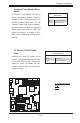
VGA Enable/Disable
Jumper Settings
Jumper Setting Denition
Pins 1-2 Enabled
Pins 2-3 Disabled