
Datasheet

Chapter 2: Installation
2-19
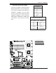
JBT1
DIMM2A
SP1
JI2C1
JI2C2
JL1
LED5
LED6
LED3
JWD1
JPG1
JPL2
JPA1
Fan 4
JD1
LED4
JWOL1
JPWF1
JAR
8-Pin PWR
I-Button
LAN
CTRL
VGA
CTRL
SI/O
SATA4
SATA3
SATA2
SATA1
SATA0
SATA5
SATA-GPIO0
Battery
SAS0
SAS1
SAS2
SAS3
SAS4
SAS5
SAS6
SAS7
PWR LED
JP1
JP2
COM2
JWOR1
JKEY1
Buzzer
BIOS
SATA-GPIO1
ITE
CTRL
LAN
CTRL
DIMM1A
DIMM2B
DIMM1B
DIMM2C
DIMM1C
LED1
SAS-GPIO0
SAS-GPIO1
24-Pin PWR
JPA2
System Status LED
Fan 1
CPU1 VRM OH LED
CPU2 VRM OH LED
Floppy
IDE
BPI
2
C
USB2/3
SMB_PS
KB/MS
COM1
VGA
FAN6
Slot4 PCI-E x4(in x8 slot)
Slot1 PCI 33MHz
SIMLC
USB0/1
LAN1
LAN2
FAN5
CPU1
CPU2
Fan 2
Fan 3
FP CTRL
USB4/5
Slot2 PCI 33MHz
Slot3 PCI 33MHz
Slot5 PCI-E x8
Slot6 PCI-E x8
Intel
5100
North Bridge
South Bridge
ICH9R
Intel
LSI
SAS
CTRL
JPL1
X7DCL-3/i
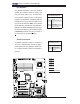
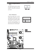
Power LED/Speaker
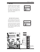
On the JD1 header, pins 1-3 are for
a power LED, and pins 4-7 are for
the speaker. See the table on the
right for speaker pin defi nitions. Note:
The speaker connector pins are for
use with an external speaker. If you
wish to use the onboard speaker, you
should close pins 6-7 with a jumper.
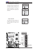
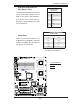
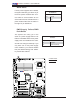
GLAN 1/2 (Giga-bit Ethernet
Ports)
Two G-bit Ethernet ports are located
at JLAN1 and JLAN2 on the I/O
backplane. These ports accept RJ45
type cables.
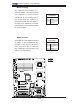
Speaker Connector
Pin Setting Defi nition
Pins 6-7 Internal Speaker
Pins 4-7 External Speaker
A
B
A. GLAN1
B. GLAN2
C. PWR LED/Speaker
GLAN1
GLAN2
C