
User`s manual


Chapter 2: Installation
2-13
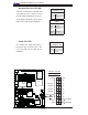
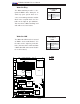
Power Button
OH/Fan Fail LED
1
NIC1 LED
Reset Button
2
HDD LED
Power LED
Reset
PWR
Vcc
Vcc
Vcc
Vcc
Ground
Ground
1920
Vcc
X
Ground
NMI
X
Vcc
PWR Fail LED
NIC2 LED
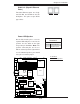
Power Button
The Power Button connection is located
on pins 1 and 2 of JF1. Momentarily
contacting both pins will power on/off
the system. This button can also be
configured to function as a suspend
button (with a setting in the BIOS - see
Chapter 4). To turn off the power when
set to suspend mode, press the button
for at least 4 seconds. Refer to the table
on the right for pin defi nitions.
Power Button
Pin Defi nitions (JF1)
Pin# Defi nition
1 Signal
2 +3V Standby
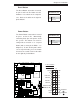
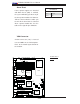
Reset Button
The Reset Button connection is located
on pins 3 and 4 of JF1. Attach it to the
hardware reset switch on the computer
case. Refer to the table on the right for
pin defi nitions.
Reset Button
Pin Defi nitions (JF1)
Pin# Defi nition
3 Reset
4 Ground
A. Reset Button
B. PWR Button
A
B
LAN1
®
S
UPER X7DVA
SCSI Chan. A
IDE1
Fan4
SCSI Chan. B
PCI 33 MHz
JD1
GLAN
CTRLR
North Bridge
COM1
ATX PWR
8-Pin PWR
24-Pin
CPU2
South
Bridge
Fan1
SATA1
Slot1
Slot2
Slot3
PCI-Exp. x8
ZCR
JPL2
Slot5
DIMM 1A (Bank 1)
DIMM 1B (Bank 1)
DIMM 1C (Bank 1)
DIMM 2A (Bank 2)
DIMM 2B (Bank 2)
DIMM 2C (Bank 2)
JBT1
KB/
Mouse
USB 0/1
5000V
BIOS
LAN2
Fan6
JPWF
JAR
PWR I
2
C
VGA
PCI-X 100 MHz
(Green Slot)
JPG1
JWD
Printer
JPL1
JI
2
C1
JI
2
C2
JWOR
Floppy
JWOL
Fan2
CPU1
LE2
LE3
LE1
USB4/5
USB2/3
JPF
Buzzer
ESB2
VGA
CTRLR
SGPIO1
SGPIO2
JL1
VGA
Memory
S I/O
COM2
J2
J8B1
J7B3
J7B2
J7B1
J1
Battery
Slot6
SIM_LP
IPMI
PCI-Exp. x4
PCI-X 100 MHz
JPA1
SCSI
CTRLR
SATA0
SATA3
SATA2
SATA5
SATA4
JPA2
JPA3
JP1
JF1
FP CNTLR
Fan3
LE4
LE5
Fan5
D31