
User`s manual


2-24
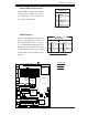
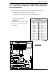
X7DVA-8/X7DVA-E User's Manual
LAN1
®
S
UPER X7DVA
SCSI Chan. A
IDE1
Fan4
SCSI Chan. B
PCI 33 MHz
JD1
GLAN
CTRLR
North Bridge
COM1
ATX PWR
8-Pin PWR
24-Pin
CPU2
South
Bridge
Fan1
SATA1
Slot1
Slot2
Slot3
PCI-Exp. x8
ZCR
JPL2
Slot5
DIMM 1A (Bank 1)
DIMM 1B (Bank 1)
DIMM 1C (Bank 1)
DIMM 2A (Bank 2)
DIMM 2B (Bank 2)
DIMM 2C (Bank 2)
JBT1
KB/
Mouse
USB 0/1
5000V
BIOS
LAN2
Fan6
JPWF
JAR
PWR I
2
C
VGA
PCI-X 100 MHz
(Green Slot)
JPG1
JWD
Printer
JPL1
JI
2
C1
JI
2
C2
JWOR
Floppy
JWOL
Fan2
CPU1
LE2
LE3
LE1
USB4/5
USB2/3
JPF
Buzzer
ESB2
VGA
CTRLR
SGPIO1
SGPIO2
JL1
VGA
Memory
S I/O
COM2
J2
J8B1
J7B3
J7B2
J7B1
J1
Battery
Slot6
SIM_LP
IPMI
PCI-Exp. x4
PCI-X 100 MHz
JPA1
SCSI
CTRLR
SATA0
SATA3
SATA2
SATA5
SATA4
JPA2
JPA3
JP1
JF1
FP CNTLR
Fan3
LE4
LE5
Fan5
D31
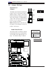
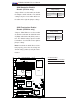
VGA Enable/Disable
Jumper Settings
Both Jumpers Defi nition
Pins 1-2 Enabled (*Default)
Pins 2-3 Disabled
A
B
A. VGA Enabled
B. PWR Fault Detect
VGA Enable/Disable
JPG1 allows you to enable or disable the
VGA port. The default position is on pins
1 and 2 to enable VGA. See the table on
the right for jumper settings.
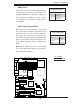
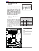
PWR Supply Failure/PWR
Fault Detect (JPWF)
The system can notify you in the event
of a power supply failure. This feature is
available when three power supply units
are installed in the chassis with one act-
ing as a backup. If you only have one
or two power supply units installed, you
should disable this (the default setting)
with JPWF to prevent false alarms.
PWR Supply PWR Fault
Jumper Settings
Jumper Setting Defi nition
Closed Enabled
Open Disabled (*Default)