
User`s manual


2-26
X7DVA-8/X7DVA-E User's Manual
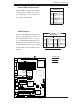
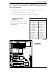
SCSI Controller Enable/
Disable (X7VA-8 only)
Jumper JPA1 is used to enable or disable
the Adaptec SCSI controller. The default
setting is on pins 1-2 to enable SCSI. See
the table on the right for jumper settings.
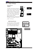
SCSI Termination Enable/
Disable (X7DVA-8 only)
Jumpers JPA2/JPA3 are used to enable
or disable termination for SCSI Channel
A (JPA2) and Channel B (JPA3) connec-
tors. The default setting is open to enable
termination. See the table on the right for
jumper settings.
Note: In order for the SCSI drives to func-
tion properly, please do not change the
default setting (enabled) set by the manu-
facturer.
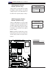
SCSI Term. Enable/Disable
Jumper Settings
Jumper Setting Defi nition
*Open (default) Enabled
Closed Disabled
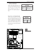
SCSI Enable/Disable
Jumper Settings
Jumper Setting Defi nition
*Pins 1-2 (Default) Enabled
Pins 2-3 Disabled
LAN1
®
S
UPER X7DVA
SCSI Chan. A
IDE1
Fan4
SCSI Chan. B
PCI 33 MHz
JD1
GLAN
CTRLR
North Bridge
COM1
ATX PWR
8-Pin PWR
24-Pin
CPU2
South
Bridge
Fan1
SATA1
Slot1
Slot2
Slot3
PCI-Exp. x8
ZCR
JPL2
Slot5
DIMM 1A (Bank 1)
DIMM 1B (Bank 1)
DIMM 1C (Bank 1)
DIMM 2A (Bank 2)
DIMM 2B (Bank 2)
DIMM 2C (Bank 2)
JBT1
KB/
Mouse
USB 0/1
5000V
BIOS
LAN2
Fan6
JPWF
JAR
PWR I
2
C
VGA
PCI-X 100 MHz
(Green Slot)
JPG1
JWD
Printer
JPL1
JI
2
C1
JI
2
C2
JWOR
Floppy
JWOL
Fan2
CPU1
LE2
LE3
LE1
USB4/5
USB2/3
JPF
Buzzer
ESB2
VGA
CTRLR
SGPIO1
SGPIO2
JL1
VGA
Memory
S I/O
COM2
J2
J8B1
J7B3
J7B2
J7B1
J1
Battery
Slot6
SIM_LP
IPMI
PCI-Exp. x4
PCI-X 100 MHz
JPA1
SCSI
CTRLR
SATA0
SATA3
SATA2
SATA5
SATA4
JPA2
JPA3
JP1
JF1
FP CNTLR
Fan3
LE4
LE5
Fan5
D31
B
A
C
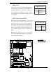
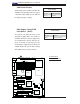
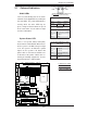
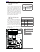
A. SCSI Enabled
B. CH. A Termination Enabled
C. CH. B Termination Enabled