
User`s manual


Chapter 2: Installation
2-27
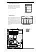
LAN1
®
S
UPER X7DVA
SCSI Chan. A
IDE1
Fan4
SCSI Chan. B
PCI 33 MHz
JD1
GLAN
CTRLR
North Bridge
COM1
ATX PWR
8-Pin PWR
24-Pin
CPU2
South
Bridge
Fan1
SATA1
Slot1
Slot2
Slot3
PCI-Exp. x8
ZCR
JPL2
Slot5
DIMM 1A (Bank 1)
DIMM 1B (Bank 1)
DIMM 1C (Bank 1)
DIMM 2A (Bank 2)
DIMM 2B (Bank 2)
DIMM 2C (Bank 2)
JBT1
KB/
Mouse
USB 0/1
5000V
BIOS
LAN2
Fan6
JPWF
JAR
PWR I
2
C
VGA
PCI-X 100 MHz
(Green Slot)
JPG1
JWD
Printer
JPL1
JI
2
C1
JI
2
C2
JWOR
Floppy
JWOL
Fan2
CPU1
LE2
LE3
LE1
USB4/5
USB2/3
JPF
Buzzer
ESB2
VGA
CTRLR
SGPIO1
SGPIO2
JL1
VGA
Memory
S I/O
COM2
J2
J8B1
J7B3
J7B2
J7B1
J1
Battery
Slot6
SIM_LP
IPMI
PCI-Exp. x4
PCI-X 100 MHz
JPA1
SCSI
CTRLR
SATA0
SATA3
SATA2
SATA5
SATA4
JPA2
JPA3
JP1
JF1
FP CNTLR
Fan3
LE4
LE5
Fan5
D31
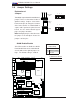
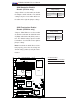
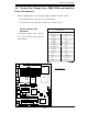
GLAN LEDs
There are two GLAN ports on the moth-
erboard. Each Gigabit Ethernet LAN port
has two LEDs. The yellow LED indicates
activity, while the other LED may be
green, orange or off to indicate the speed
of the connection. See the tables at right
for more information.
2-7 Onboard Indicators
A
B
C
A. GLAN Port1 LEDs
B. GLAN Port2 LEDs
C. Onboard PWR LED
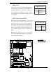
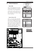
Activity
LED
GLAN Link Indicator
LED Settings
LED Color Defi nition
Off No Connection or 10 Mbps
Green 100 Mbps
Amber 1 Gbps
Link
LED
GLAN Activity Indicator
Color Status Defi nition
Yellow Flashing Active
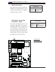
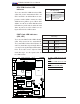
System Status LED
There is an System Status LED (D31)
located on the motherboard. When D31 is
off, the system is off. When the green light
is on, the system is on. When the yellow
light is on, the system is off, but the AC
power cable is still connected. Make sure
to disconnect the power cable before re-
moving or installing components. See the
layout below for the LED location.
System Status LED Indicator (D31)
LED Settings
LED Color Defi nition
Off System Off
Green System On
Yellow System off, PWR Cable
Connected
Red System on, problem(s)
in PWR
(*Rear View: When viewing from
the rear side of the chassis)