
User`s manual


1-4
X7SBA User’s Manual
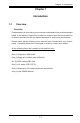
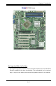
Important Notes to the User
• Jumpers not indicated are for testing only.
• See Chapter 2 for detailed information on jumpers, I/O ports and JF1 Front
Panel Connections.
• " " indicates the location of "Pin 1".
• When the LE1 LED is on, the 5V Standby PWR is on. Maker sure to turn off
the power before installing or removing components.
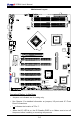
Motherboard Layout
X7SBA
4
Battery
Slot1 PCI 33 MHz
SI/O
JPL1
LAN
CTRL
Intel
Slot7 PCI-E x8 on x16
Slot6 PCI-X 100/133 MHz
Slot5 PCI-X 100/133 MHz
Slot4 PCI 33 MHz
Slot3 PCI 33 MHz
Slot2 PCI 33 MHz
LAN
CTRL
Intel
J28
KB/MS
J11
USB0/1
COM1
J7
VGA
LAN1
LAN2
JLAN1
JLAN2
JPW1
Fan6
AT X 24-Pin PWR
CPU Fan
SMB PS
PWR Fail
JAR
Fan1
8-Pin PWR
JPW2
CPU
3210
Xeon
3000
DIMM2B
DIMM1B
DIMM2A
DIMM1
DIMM2
DIMM3
DIMM4
Fan 5
JLED1
JF1
LE1
JOH
Fan2
Fan3
JL1
JWD
JD1
Speaker
Floppy
Fan4
J48
JBT1
JWOR
I-SATA2
JWOL
J44
J45
JI
2
C1JI
2
C2
COM2
Printer
SIMSO (IPMI 2.0)
USB8/9 USB6/7
BP USB11
FP CTRL
JPWF
R171
Q15
DIMM1A
JPL2
I-SATA0
PXH-V
I-SATA1
I-SATA3
I-SATA4
I-SATA5
Buzzer
Intel
Intel
J29
J30
T-SGPIO1
T-SGPIO2
JPG1
ICH9R
SPKR1
MCH
JUSB1
1
JUSB2