
User`s manual

Chapter 2: Installation
2-7
X7SBA
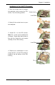
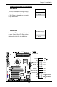
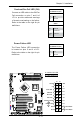
To Install:
Insert module verti-
cally and press it
down until it snaps
into place. Pay atten-
tion to the notch.
Figure 2-1. Installing DIMM into Slot
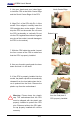
To Remove:
Use your thumbs to
gently push each
release tab outward
to release the DIMM
from the slot.
Top View Of DDR2 Slot
DDR2
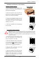
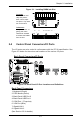
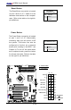
2-5 Control Panel Connectors/IO Ports
The I/O ports are color coded in conformance with the PC 99 specication. See
Figure 2-2 below for the colors and locations of the various I/O ports.
Back Panel Connectors/IO Ports
Figure2-2.BackPanelI/OPortLocationsandDenitions
Back Panel Connectors
1. Keyboard (Purple)
2. PS/2 Mouse (Green)
3. Back Panel USB Port 0
4. Back Panel USB Port 1
5. COM Port 1 (Turquoise)
6. VGA Port (Blue)
7. Gigabit LAN 1
8. Gigabit LAN 2
(See Section 2-5 for details.)
1
2
3
4
5
6
7
8