
User`s manual

2-8
X7SBA User's Manual
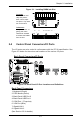
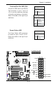
Front Control Panel
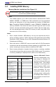
JF1 contains header pins for various buttons and indicators that are normally
located on a control panel at the front of the chassis. These connectors are de-
signed specically for use with Supermicro server chassis. See Figure 2-4 for the
descriptions of the various control panel buttons and LED indicators. Refer to the
following section for descriptions and pin denitions.
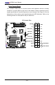
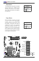
JF1 Header Pins
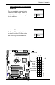
Power Button
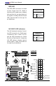
OH/Fan Fail LED
1
NIC1 LED
Reset Button
2
HDD LED
Power LED
Reset
PWR
Vcc
Vcc
Vcc
Vcc
Ground
Ground
1920
Vcc
X
Ground
NMI
X
Vcc
PWR Fail LED
NIC2 LED
X7SBA