
User`s manual

2-10
X7SBA User's Manual
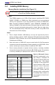
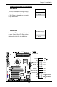
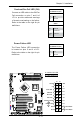
NIC1/NIC2 LED Indicators
The NIC (Network Interface Control-
ler) LED connection for GLAN port1
is located on pins 11 and 12 of JF1
and the LED connection for GLAN
Port2 is on Pins 9 and 10. Attach the
NIC LED cables to display network
activity status. Refer to the table on
the right for pin denitions.
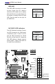
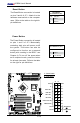
HDD LED
The HDD LED connection is located
on pins 13 and 14 of JF1. Attach a
hard drive LED cable here to display
disk activities (for any hard drives on
the system, including Serial ATA and
IDE). See the table on the right for
pin denitions.
HDD LED
PinDenitions(JF1)
Pin# Denition
13 +5V
14 HD Active
GLAN1/2 LED
PinDenitions(JF1)
Pin# Denition
9/11 Vcc
10/12 Ground
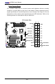
Power Button
OH/Fan Fail LED
1
NIC1 LED
Reset Button
2
HDD LED
Power LED
Reset
PWR
Vcc
Vcc
Vcc
Vcc
Ground
Ground
1920
Vcc
X
Ground
NMI
X
Vcc
PWR Fail LED
NIC2 LED
A
B
C
A. HDD LED
B. NIC1 LED
C. NIC2 LED
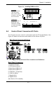
X7SBA
4
Battery
Slot1 PCI 33 MHz
SI/O
JPL1
LAN
CTRL
Intel
Slot7 PCI-E x8 on x16
Slot6 PCI-X 100/133 MHz
Slot5 PCI-X 100/133 MHz
Slot4 PCI 33 MHz
Slot3 PCI 33 MHz
Slot2 PCI 33 MHz
LAN
CTRL
Intel
KB/MS
USB0/1
COM1
VGA
LAN1
LAN2
Fan6
ATX 24-Pin PWR
CPU Fan
SMB PS
PWR Fail
JAR
Fan1
8-Pin PWR
CPU
MCH
3210
Xeon
3000
DIMM2B
DIMM1B
DIMM2A
DIMM1
DIMM2
DIMM3
DIMM4
Fan 5
JLED1
LE1
JOH
Fan2
Fan3
JL1
JWD
JD1
Floppy
Fan4
JBT1
JWOR
I-SATA2
JWOL
JI
2
C1JI
2
C2
COM2
Printer
SIMSO (IPMI 2.0)
USB8/9 USB6/7
BP USB11
FP CTRL
R171
Q15
DIMM1A
JPL2
I-SATA0
PXH-V
I-SATA1
I-SATA3
I-SATA4
I-SATA5
Buzzer
Intel
Intel
T-SGPIO1
T-SGPIO2
JPG1
ICH9R
JUSB1
JUSB2