
User`s manual


2-14
X7SBA User's Manual
X7SBA
4
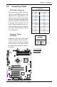
Battery
Slot1 PCI 33 MHz
SI/O
JPL1
LAN
CTRL
Intel
Slot7 PCI-E x8 on x16
Slot6 PCI-X 100/133 MHz
Slot5 PCI-X 100/133 MHz
Slot4 PCI 33 MHz
Slot3 PCI 33 MHz
Slot2 PCI 33 MHz
LAN
CTRL
Intel
KB/MS
USB0/1
COM1
VGA
LAN1
LAN2
Fan6
ATX 24-Pin PWR
CPU Fan
SMB PS
PWR Fail
JAR
Fan1
8-Pin PWR
CPU
MCH
3210
Xeon
3000
DIMM2B
DIMM1B
DIMM2A
DIMM1
DIMM2
DIMM3
DIMM4
Fan 5
JLED1
LE1
JOH
Fan2
Fan3
JL1
JWD
JD1
Floppy
Fan4
JBT1
JWOR
I-SATA2
JWOL
JI
2
C1JI
2
C2
COM2
Printer
SIMSO (IPMI 2.0)
USB8/9 USB6/7
BP USB11
FP CTRL
R171
Q15
DIMM1A
JPL2
I-SATA0
PXH-V
I-SATA1
I-SATA3
I-SATA4
I-SATA5
Buzzer
Intel
Intel
T-SGPIO1
T-SGPIO2
JPG1
ICH9R
JUSB1
JUSB2
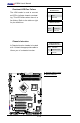
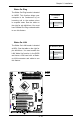
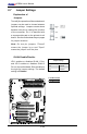
Chassis Intrusion
A Chassis Intrusion header is located
at JL1. Attach the appropriate cable to
inform you of a chassis intrusion.
Chassis Intrusion
PinDenitions(JL1)
Pin# Denition
1 Intrusion Input
2 Ground
A
B
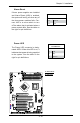
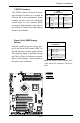
Overheat LED/Fan Failure
The JOH header is used to connect
an LED to indicate chassis overheat-
ing. This LED blinks when there is a
fan failure. Refer to the table on right
for pin denitions.
Overheat LED
PinDenitions
Pin# Denition
1 5vDC
2 OH Active
OH/Fan Fail LED
State Message
Solid Overheat
Blinking Fan Fail
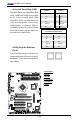
A. Overheat LED/Fan Failure
B. Chassis Intrusion