
User`s manual


2-18
X7SBA User's Manual
X7SBA
4
Battery
Slot1 PCI 33 MHz
SI/O
JPL1
LAN
CTRL
Intel
Slot7 PCI-E x8 on x16
Slot6 PCI-X 100/133 MHz
Slot5 PCI-X 100/133 MHz
Slot4 PCI 33 MHz
Slot3 PCI 33 MHz
Slot2 PCI 33 MHz
LAN
CTRL
Intel
KB/MS
USB0/1
COM1
VGA
LAN1
LAN2
Fan6
ATX 24-Pin PWR
CPU Fan
SMB PS
PWR Fail
JAR
Fan1
8-Pin PWR
CPU
MCH
3210
Xeon
3000
DIMM2B
DIMM1B
DIMM2A
DIMM1
DIMM2
DIMM3
DIMM4
Fan 5
JLED1
LE1
JOH
Fan2
Fan3
JL1
JWD
JD1
Floppy
Fan4
JBT1
JWOR
I-SATA2
JWOL
JI
2
C1JI
2
C2
COM2
Printer
SIMSO (IPMI 2.0)
USB8/9 USB6/7
BP USB11
FP CTRL
R171
Q15
DIMM1A
JPL2
I-SATA0
PXH-V
I-SATA1
I-SATA3
I-SATA4
I-SATA5
Buzzer
Intel
Intel
T-SGPIO1
T-SGPIO2
JPG1
ICH9R
JUSB1
JUSB2
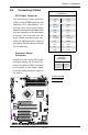
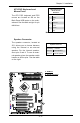
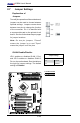
Fan Headers
The X7SBA has six fan connections
(Fan1 to Fan6). Fan6 is designated
the CPU Cooling Fan. Note: all these
fans are 4-pin fans. However, Pins
1-3 of the fan headers are backward
compatible with the traditional 3-pin
fans. The onboard fan speeds are
controlled by Thermal Management
under Hardware Monitoring in the
BIOS. When using Thermal Manage-
ment settings, please use all 3-pin
fans or all 4-pin fans on the mother-
board. Please do not use 3-pin fans
and 4-pin fans on the same board.
The default setting is "Disabled"
which will allow the onboard fans to
run at full speed. See the table on
the right for pin denitions.
Fan Header
PinDenitions
Pin# Denition
1 Ground (Black)
2 +12V (Red)
3 Tachometer
4 PWM_Control
D
A
B
C
A. Fan 1
B. Fan 2
C. Fan 3
D. Fan 4
E. Fan 5
F. Fan 6 (CPU Fan)
DF
E