
User`s manual


Chapter 2: Installation
2-19
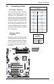
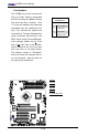
X7SBA
4
Battery
Slot1 PCI 33 MHz
SI/O
JPL1
LAN
CTRL
Intel
Slot7 PCI-E x8 on x16
Slot6 PCI-X 100/133 MHz
Slot5 PCI-X 100/133 MHz
Slot4 PCI 33 MHz
Slot3 PCI 33 MHz
Slot2 PCI 33 MHz
LAN
CTRL
Intel
KB/MS
USB0/1
COM1
VGA
LAN1
LAN2
Fan6
ATX 24-Pin PWR
CPU Fan
SMB PS
PWR Fail
JAR
Fan1
8-Pin PWR
CPU
MCH
3210
Xeon
3000
DIMM2B
DIMM1B
DIMM2A
DIMM1
DIMM2
DIMM3
DIMM4
Fan 5
JLED1
LE1
JOH
Fan2
Fan3
JL1
JWD
JD1
Floppy
Fan4
JBT1
JWOR
I-SATA2
JWOL
JI
2
C1JI
2
C2
COM2
Printer
SIMSO (IPMI 2.0)
USB8/9 USB6/7
BP USB11
FP CTRL
R171
Q15
DIMM1A
JPL2
I-SATA0
PXH-V
I-SATA1
I-SATA3
I-SATA4
I-SATA5
Buzzer
Intel
Intel
T-SGPIO1
T-SGPIO2
JPG1
ICH9R
JUSB1
JUSB2
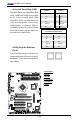
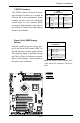
Wake-On-Ring
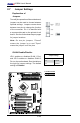
The Wake-On-Ring header is located
at JWOR. This function allows your
computer to be "awakened" by an
incoming call to the modem when
in suspend state. See the table on
the right for pin denitions. You must
have a Wake-On-Ring card and cable
to use this feature.
Wake-On-LAN
The Wake-On-LAN header is located
at WOL. See the table on the right for
pin denitions. You must enable the
LAN Wake-Up function in the BIOS
and have a LAN card with a Wake-
on-LAN connector and cable to use
this feature.
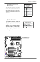
Wake-On-LAN
PinDenitions(WOL)
Pin# Denition
1 +5V Standby
2 Ground
3 Wake-up
Wake-On-Ring
PinDenitions
(JWOR)
Pin# Denition
1 Ground (Black)
2 Wake-up
A
B
A. WOR
B. WOL