
User`s manual


Chapter 2: Installation
2-21
X7SBA
4
Battery
Slot1 PCI 33 MHz
SI/O
JPL1
LAN
CTRL
Intel
Slot7 PCI-E x8 on x16
Slot6 PCI-X 100/133 MHz
Slot5 PCI-X 100/133 MHz
Slot4 PCI 33 MHz
Slot3 PCI 33 MHz
Slot2 PCI 33 MHz
LAN
CTRL
Intel
KB/MS
USB0/1
COM1
VGA
LAN1
LAN2
Fan6
ATX 24-Pin PWR
CPU Fan
SMB PS
PWR Fail
JAR
Fan1
8-Pin PWR
CPU
MCH
3210
Xeon
3000
DIMM2B
DIMM1B
DIMM2A
DIMM1
DIMM2
DIMM3
DIMM4
Fan 5
JLED1
LE1
JOH
Fan2
Fan3
JL1
JWD
JD1
Floppy
Fan4
JBT1
JWOR
I-SATA2
JWOL
JI
2
C1JI
2
C2
COM2
Printer
SIMSO (IPMI 2.0)
USB8/9 USB6/7
BP USB11
FP CTRL
R171
Q15
DIMM1A
JPL2
I-SATA0
PXH-V
I-SATA1
I-SATA3
I-SATA4
I-SATA5
Buzzer
Intel
Intel
T-SGPIO1
T-SGPIO2
JPG1
ICH9R
JUSB1
JUSB2
C
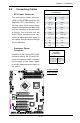
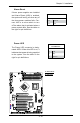
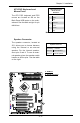
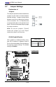
T-SGPIO Headers
Two SGPIO (Serial General Purpose
Input/Output) headers are located at
J29 and J30 on the motherboard. These
headers provide serial link interfacing
co nnec ti ons fo r the onboar d S ATA
connectors. See the table on the right for
pin denitions. Refer to the board layout
below for the location.
Note: NC= No Connections
SGPIO
PinDenitions
Pin# Denition Pin Denition
1 NC 2 NC
3 Ground 4 DATA Out
5 Load 6 Ground
7 Clock 8 NC
A
A. T-SGPIO1
B. T-SGPIO2
C. PWR Fault
B
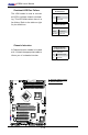
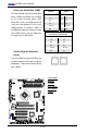
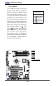
Power Fault (PWR Supply
Failure)
Connect a cable from your power sup-
ply to the Power Fail header (JPWF) to
provide warnings of power supply failure.
This warning signal is passed through
the PWR_LED pin to indicate of a power
failure on the chassis. See the table on
the right for pin denitions.
Note: This feature is only available when
using Supermicro redundant power sup-
plies.
PWR Supply Fail LED
PinDenitions
Pin# Denition
1 PWR 1: Fail
2 PWR 2: Fail
3 PWR 3: Fail
4 Signal: Alarm Reset