
User`s manual


Chapter 2: Installation
2-25
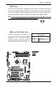
USB Wake-Up
Use JPUSB jumpers to enable the function
of "System Waking-Up via USB devices".
These jumpers allow you to "wake-up"
the system by pressing a key on the USB
keyboard or by clicking the USB mouse of
your system. The JPUSB jumpers are used
together with the USB Wake-Up function in
the BIOS. Enable both the jumpers and the
BIOS setting to enable this function. See
the tables on the right for jumper settings
and jumper connections.
Notes:
1. JPUSB1 is for Back Panel USB ports:
0/1, and JPUSB2 is for Front Panel USB
ports: 6/7, 8/9, 11. (Default: JPUSB1: En-
abled, JPUSB2: Disabled.)
2. When the "USB Wake-Up" function is
enabled in the BIOS and the selected USB
ports are also enabled via the JPUSB jump-
ers, please be sure to remove all other USB
devices from the USB ports whose USB
jumpers are set to "Disabled" before the
system goes into the standby mode.
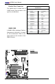
USB Wake-Up (JPUSB2)
Jumper Settings
Jumper Setting Denition
Pins 1-2 Enabled
Pins 2-3 Disabled (Default)
USB Wake-Up (JPUSB1)
Jumper Settings
Jumper Setting Denition
Pins 1-2 Enabled (Default)
Pins 2-3 Disabled
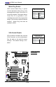
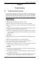
X7SBA
4
Battery
Slot1 PCI 33 MHz
SI/O
JPL1
LAN
CTRL
Intel
Slot7 PCI-E x8 on x16
Slot6 PCI-X 100/133 MHz
Slot5 PCI-X 100/133 MHz
Slot4 PCI 33 MHz
Slot3 PCI 33 MHz
Slot2 PCI 33 MHz
LAN
CTRL
Intel
KB/MS
USB0/1
COM1
VGA
LAN1
LAN2
Fan6
ATX 24-Pin PWR
CPU Fan
SMB PS
PWR Fail
JAR
Fan1
8-Pin PWR
CPU
MCH
3210
Xeon
3000
DIMM2B
DIMM1B
DIMM2A
DIMM1
DIMM2
DIMM3
DIMM4
Fan 5
JLED1
LE1
JOH
Fan2
Fan3
JL1
JWD
JD1
Floppy
Fan4
JBT1
JWOR
I-SATA2
JWOL
JI
2
C1JI
2
C2
COM2
Printer
SIMSO (IPMI 2.0)
USB8/9 USB6/7
BP USB11
FP CTRL
R171
Q15
DIMM1A
JPL2
I-SATA0
PXH-V
I-SATA1
I-SATA3
I-SATA4
I-SATA5
Buzzer
Intel
Intel
T-SGPIO1
T-SGPIO2
JPG1
ICH9R
JUSB1
JUSB2
A
B
A. JPUSB1
B. JPUSB2