
User`s manual


2-26
X7SBA User's Manual
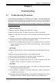
X7SBA
4
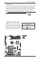
Battery
Slot1 PCI 33 MHz
SI/O
JPL1
LAN
CTRL
Intel
Slot7 PCI-E x8 on x16
Slot6 PCI-X 100/133 MHz
Slot5 PCI-X 100/133 MHz
Slot4 PCI 33 MHz
Slot3 PCI 33 MHz
Slot2 PCI 33 MHz
LAN
CTRL
Intel
KB/MS
USB0/1
COM1
VGA
LAN1
LAN2
Fan6
ATX 24-Pin PWR
CPU Fan
SMB PS
PWR Fail
JAR
Fan1
8-Pin PWR
CPU
MCH
3210
Xeon
3000
DIMM2B
DIMM1B
DIMM2A
DIMM1
DIMM2
DIMM3
DIMM4
Fan 5
JLED1
LE1
JOH
Fan2
Fan3
JL1
JWD
JD1
Floppy
Fan4
JBT1
JWOR
I-SATA2
JWOL
JI
2
C1JI
2
C2
COM2
Printer
SIMSO (IPMI 2.0)
USB8/9 USB6/7
BP USB11
FP CTRL
R171
Q15
DIMM1A
JPL2
I-SATA0
PXH-V
I-SATA1
I-SATA3
I-SATA4
I-SATA5
Buzzer
Intel
Intel
T-SGPIO1
T-SGPIO2
JPG1
ICH9R
JUSB1
JUSB2
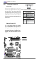
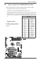
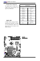
GLAN LEDs
There are two GLAN ports on the moth-
erboard. Each Gigabit Ethernet LAN port
has two LEDs. The yellow (right) LED
indicates activity while the other LED may
be green, amber or off to indicate the
speed of the connection. See the table at
right for the functions associated with the
second LED.
2-8 Onboard Indicators
Activity
(Right)
L i n k
(Left)
GLAN Link LED (Left)
Speed Indicator
LED Color Denition
Off 10Mbps or No Connection
Green 100 Mbps
Amber 1 Gbps
GLAN Yellow LED (Right)
Activity LED Indicator
LED Color Denition
Yellow Flashing: Active, running
@10Mbps, 100Mbps or
1 Gbps
A
B
A. GLAN1 Port
B. GLAN2 Port
C. Onboard LED
Rear View
(When viewing from the back of the system)
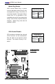
Onboard Power LED
LE1 is an Onboard Power LED located
on the motherboard. When this LED is
lit, the onboard power is on. Be sure to
turn off the system and unplug the power
cord before removing or installing com-
ponents. See the layout below for the
LED location.
C