X8DT6 X8DTE X8DT6-F X8DTE-F USER’S MANUAL Revision 1.
The information in this User’s Manual has been carefully reviewed and is believed to be accurate. The vendor assumes no responsibility for any inaccuracies that may be contained in this document, makes no commitment to update or to keep current the information in this manual, or to notify any person or organization of the updates. Please Note: For the most up-to-date version of this manual, please see our website at www.supermicro.com. Super Micro Computer, Inc.
Preface Preface About this Manual This manual is written for system integrators, PC technicians and knowledgeable PC users. It provides information for the installation and use of the X8DT6/ X8DT6-F/X8DTE/X8DTE-F motherboard.
X8DT6/X8DT6-F/X8DTE/X8DTE-F User's Manual Warning: Important information given to ensure proper system installation or to prevent damage to the components. Note: Additional Information given to differentiate various models or to ensure correct system setup.
Contacting Supermicro Contacting Supermicro Headquarters Address: Super Micro Computer, Inc. 980 Rock Ave. San Jose, CA 95131 U.S.A. Tel: +1 (408) 503-8000 Fax: +1 (408) 503-8008 Email: marketing@supermicro.com (General Information) support@supermicro.com (Technical Support) Web Site: www.supermicro.com Europe Address: Super Micro Computer B.V. Het Sterrenbeeld 28, 5215 ML 's-Hertogenbosch, The Netherlands Tel: +31 (0) 73-6400390 Fax: +31 (0) 73-6416525 Email: sales@supermicro.
X8DT6/X8DT6-F/X8DTE/X8DTE-F User's Manual Table of Contents Preface Chapter 1 Introduction 1-1 Overview ......................................................................................................... 1-1 1-2 Chipset Overview ............................................................................................ 1-9 1-3 Special Features ........................................................................................... 1-10 1-4 PC Health Monitoring .............................
Table of Contents Power LED .............................................................................................. 2-17 HDD LED.................................................................................................. 2-18 NIC1/NIC2 LED Indicators ....................................................................... 2-18 Overheat (OH)/Fan Fail LED.................................................................... 2-19 Power Fail LED .......................................................
X8DT6/X8DT6-F/X8DTE/X8DTE-F User's Manual Chapter 3 Troubleshooting 3-1 Troubleshooting Procedures ........................................................................... 3-1 Before Power On ............................................................................................ 3-1 No Power ........................................................................................................ 3-1 No Video ...........................................................................................
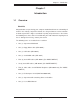
Chapter 1: Introduction Chapter 1 Introduction 1-1 Overview Checklist Congratulations on purchasing your computer motherboard from an acknowledged leader in the industry. Supermicro boards are designed with the utmost attention to detail to provide the highest standards in quality and performance. Check that the following items have all been included with your motherboard. If anything listed here is damaged or missing, contact your retailer. The following items are included in the retail box.
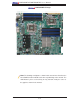
X8DT6/X8DT6-F/X8DTE/X8DTE-F User's Manual X8DT6/X8DT6-F Image Note: The drawings and pictures shown in this manual were based on the latest PCB Revision available at the time of publishing of the manual. The motherboard you’ve received may or may not look exactly the same as the graphics shown in the manual.
Chapter 1: Introduction KB/MOUSE X8DT6/X8DT6-F/X8DTE/X8DTE-F Layout FAN5 P1-DIMM3A JPI2C1 IPMI LAN FAN1 P1-DIMM2B P1-DIMM1A P1-DIMM1B FAN7 CPU1 Fan CPU2 JF1 VGA JPW3 P1-DIMM2A COM1 USB 0/1 FAN6 JPW2 JPW1 P1-DIMM3B PHY LE1 LAN1 CPU1 CP FAN2 P2-DIMM1B JOH1 JD1 LAN2 P2-DIMM1A P2-DIMM2B P2-DIMM2A P2-DIMM3B FAN8/ CPU2 Fan P2-DIMM3A SLOT7 PCI-E 2.0 X8 FAN3 X8DT6/E Series Rev. 2.01 SP1 LAN CTRL JPL1 SLOT6 PCI-E 2.0 X8 Intel 5520 SLOT5 PCI-E 2.0 X8 LAN CTRL SIO SLOT4 PCI-E 2.
X8DT6/X8DT6-F/X8DTE/X8DTE-F User's Manual KB/MOUSE Motherboard Layout FAN5 P1-DIMM3A JPI2C1 IPMI LAN USB 0/1 FAN6 JPW2 JPW1 P1-DIMM3B JPW3 FAN1 P1-DIMM2A P1-DIMM2B P1-DIMM1B FAN7 CPU1 Fan CPU2 JF1 VGA COM1 P1-DIMM1A PHY LE1 LAN1 CPU1 CP FAN2 P2-DIMM1B JOH1 JD1 LAN2 P2-DIMM1A P2-DIMM2B P2-DIMM2A P2-DIMM3B FAN8/ CPU2 Fan P2-DIMM3A SLOT7 PCI-E 2.0 X8 FAN3 X8DT6/E Series Rev. 2.01 SP1 LAN CTRL JPL1 SLOT6 PCI-E 2.0 X8 Intel 5520 SLOT5 PCI-E 2.0 X8 SIO SLOT4 PCI-E 2.
Chapter 1: Introduction X8DT6/E-F Quick Reference Jumper Description Default Setting JBT1 CMOS Clear (See Section 2-7) JI2C1/JI2C2 SMB to PCI Slots 2-3 (Disabled) JPG1 VGA Enable Pins 1-2 (Enabled) JPL1/JPL2 LAN Ports 1/2 Enable Pins 1-2 (Enabled) (For a Rev. 1.
X8DT6/X8DT6-F/X8DTE/X8DTE-F User's Manual Motherboard Features CPU • Two Intel® 5500/5600 Series (LGA 1366) processors; each processor supports two full-width Intel QuickPath Interconnect (QPI) links with a total of up to 51.2 GB/s Data Transfer Rate (6.4 GT/s per direction) Memory • Twelve 240-pin DIMM sockets support up to 192 GB of DDR3 Registered ECC or up to 48 GB of Unbuffered ECC/Non ECC Memory (See Section 2-4 in Chapter 2 for DIMM Slot Population.
Chapter 1: Introduction • System resource alert via Supero Doctor III ACPI Features • • • • Slow blinking LED for suspend state indicator Main switch override mechanism ACPI Power Management Keyboard Wakeup from Soft-off Onboard I/O • Intel ICH10R supports six SATA2 ports (with RAID0, RAID1, RAID10, RAID5 supported in the Windows OS Environment and RAID0, RAID1, RAID10 in the Linux) (Note 1) • LSI 2008 SATA 2 supports eight SAS ports with RAID 5 optional, using RAIDKey (Part# AOC-IMRRAKey-2008-LSI
X8DT6/X8DT6-F/X8DTE/X8DTE-F User's Manual #0-6 #0-5 #0-4 #0-3 #0-2 #0-1 Slot 6 PCI-E X8 DDR3 800/1066/1333 IOH-36D Ports PCI-E X4 #1-2 Ports #9-10 Port #0 Optional DMI PCI-E X4 PCI-E X1 LANE5 Intel ICH10R #5 #4 #3 #2 #1 #0 3.0 Gb/S LANE6 VGA ~# #0 SB USB 2.
Chapter 1: Introduction 1-2 Chipset Overview Built upon the capability of the Intel 5520 platform, the X8DT6/X8DT6-F/X8DTE/ X8DTE-F motherboard provides the performance and feature set required for dual-processor-based high-end servers optimized for High Performance Computing (HPC), Clustering, and intensive applications. The 5520 platform consists of the 5500/5600 Series (LGA 1366) processor, the 5520 (IO Hub), and the ICH10R (South Bridge).
X8DT6/X8DT6-F/X8DTE/X8DTE-F User's Manual 1-3 Special Features Recovery from AC Power Loss BIOS provides a setting for you to determine how the system will respond when AC power is lost and then restored to the system. You can choose for the system to remain powered off (in which case you must hit the power switch to turn it back on) or for it to automatically return to a power- on state. See the Advanced BIOS Setup section to change this setting. The default setting is Last State.
Chapter 1: Introduction environment or used with Supero Doctor II in Linux. Supero Doctor is used to notify the user of certain system events. You can also configure Supero Doctor to provide you with warnings when the system/CPU temperatures, voltages and fan speeds go beyond a pre-defined range. 1-5 ACPI Features ACPI stands for Advanced Configuration and Power Interface.
X8DT6/X8DT6-F/X8DTE/X8DTE-F User's Manual (WOL) to connect to the 3-pin header on a Network Interface Card (NIC) that has WOL capability. In addition, an onboard LAN controller can also support WOL without any connection to the WOL header. The 3-pin WOL header is to be used with a LAN add-on card only. Note: Wake-On-LAN requires an ATX 2.01 (or above) compliant power supply. 1-6 Power Supply As with all computer products, a stable power source is necessary for proper and reliable operation.
Chapter 1: Introduction baud rate generator, complete modem control capability and a processor interrupt system. Both UARTs provide legacy speed with baud rate of up to 115.2 Kbps as well as an advanced speed with baud rates of 250 K, 500 K, or 1 Mb/s, which support higher speed modems. The Super I/O provides functions that comply with ACPI (Advanced Configuration and Power Interface), which includes support of legacy and ACPI power management through an SMI or SCI function pin.
X8DT6/X8DT6-F/X8DTE/X8DTE-F User's Manual Notes 1-14
Chapter 2: Installation Chapter 2 Installation 2-1 Static-Sensitive Devices Electrostatic Discharge (ESD) can damage electronic components. To prevent damage to your system board, it is important to handle it very carefully. The following measures are generally sufficient to protect your equipment from ESD. Precautions • Use a grounded wrist strap designed to prevent static discharge. • Touch a grounded metal object before removing the board from the antistatic bag.
X8DT6/X8DT6-F/X8DTE/X8DTE-F User's Manual 2-2 Motherboard Installation All motherboards have standard mounting holes to fit different types of chassis. Make sure that the locations of all the mounting holes for both motherboard and chassis match. Although a chassis may have both plastic and metal mounting fasteners, metal ones are highly recommended because they ground the motherboard to the chassis. Make sure that the metal standoffs click in or are screwed in tightly.
Chapter 2: Installation 2-3 Processor and Heatsink Installation When handling the processor package, avoid placing direct pressure on ! the label area of the fan. Notes: 1. Always connect the power cord last and always remove it before adding, removing or changing any hardware components. Make sure that you install the processor into the CPU socket before you install the CPU heatsink. 2. Make sure to install the motherboard into the chassis before you install the CPU heatsink and heatsink fans. 3.
X8DT6/X8DT6-F/X8DTE/X8DTE-F User's Manual CPU Socket CPU 1. After removing the plastic cap, using your thumb and the index finger, hold the CPU at the north and south center edges. 2. Align the CPU key, the semicircle cutout, against the socket key, the notch below the gold Socket Keys color dot on the side of the socket. 3. Once both the CPU and the socket are aligned, carefully lower the CPU straight down into the socket.
Chapter 2: Installation Installing a CPU Heatsink 1. Do not apply any thermal grease to the heatsink or the CPU die because the required amount has already been applied. Screw#1 Screw#2 2. Place the heatsink on top of the CPU so that the four mounting holes are aligned with those on the retention mechanism. Screw#1 Install Screw#1 3. Install two diagonal screws (ie the #1 and the #2 screws) and tighten them until just snug (-do not fully tighten the screws to avoid possible damage to the CPU.) 4.
X8DT6/X8DT6-F/X8DTE/X8DTE-F User's Manual Removing the Heatsink Warning: We do not recommend that the CPU or the heatsink be removed. However, if you do need to remove the heatsink, please follow the instructions below to uninstall the heatsink and prevent damage to the CPU or other components. 1. Unplug the power cord from the power supply. 2. Disconnect the heatsink fan wires from the CPU fan header. 3.
Chapter 2: Installation 2-4 Memory Installation Note: Check the Supermicro web site for recommended memory modules. CAUTION Exercise extreme care when installing or removing DIMM modules to prevent any possible damage. Also note that the memory is interleaved to improve performance (See step 1). DIMM Installation 1. Insert the desired number of DIMMs into the memory slots, starting with DIMM #P1-DIMM1A. When populating two DIMM modules within a channel, always start with Bank1 first.
X8DT6/X8DT6-F/X8DTE/X8DTE-F User's Manual Memory Support The X8DT6/X8DT6-F/X8DTE/X8DTE-F supports up to 192 GB of Registered ECC or up to 48 GB of Unbuffered ECC/Non ECC DDR3 1333 MHz/1066 MHz/800 MHz in 12 DIMMs. Please note that Memory Speed support is also depending on the type of CPU used in the motherboard. DIMM Module Population Configuration For memory to work properly, follow the tables below for memory installation.
Chapter 2: Installation Memory Support for the motherboards w/5500 Series Processors installed RDIMM Population for the Motherboard w/5500 Processors Installed DIMM Slots per Channel DIMMs Populated per Channel DIMM Type (Reg.= Registered) Speeds (in MHz) Ranks per DIMM (any combination; SR=Single Rank, DR=Dual Rank, QR=Quad Rank) 2 1 Reg. DDR3 ECC 800,1066,1333 SR or DR 2 1 Reg. DDR3 ECC 800,1066 QR 2 2 Reg. DDR3 ECC 800,1066 Mixing SR, DR 2 2 Reg.
X8DT6/X8DT6-F/X8DTE/X8DTE-F User's Manual • 1.35V DIMMs 1.35V RDIMM Population for the Motherboard w/5600 Processors Installed DIMM Slots per Channel DIMMs Populated per Channel DIMM Type (Reg.=Registered) Speeds (in MHz) Ranks per DIMM (any combination; SR=Single Rank, DR=Dual Rank, QR=Quad Rank) 2 1 Reg. DDR3 ECC 800,1066,1333 SR or DR 2 1 Reg. DDR3 ECC 800 (Note 1) QR 2 2 Reg. DDR3 ECC 800,1066 (Note 2) Mixing SR, DR 2 2 Reg.
Chapter 2: Installation 2-5 Control Panel Connectors/IO Ports The I/O ports are color coded in conformance with the PC 99 specification. See the picture below for the colors and locations of the various I/O ports. 1. Back Panel Connectors/IO Ports 2 5 1 4 X8DT6/E Series Rev. 2.01 6 7 3 Back Panel I/O Port Locations and Definitions Back Panel Connectors 1. Keyboard (Purple) 2. PS/2 Mouse (Green) 3. Back Panel USB Port 0 4. Back Panel USB Port 1 5. IPMI_LAN (X8DT6-F/X8DTE-F only) 6.
X8DT6/X8DT6-F/X8DTE/X8DTE-F User's Manual ATX PS/2 Keyboard and PS/2 PS/2 Keyboard/Mouse Pin Definitions Mouse Ports The ATX PS/2 keyboard and PS/2 PS2 Keyboard PS2 Mouse mouse are located next to the Back Pin# Definition Pin# Definition Panel USB Ports 0~1 and IPMI_LAN 1 KB Data 1 Mouse Data on the motherboard. See the table at right for pin definitions.
Chapter 2: Installation Universal Serial Bus (USB) Back Panel USB (USB 0/1) Two Universal Serial Bus ports (USB 0 and USB 1) are located on the I/O Front Panel USB (USB 2/3) Pin# Definitions Pin# Definition 1 Vcc 2 Data- 3 Data+ 4 Ground 5 NA 1 +5V back panel. Additionally, six USB con- 2 PO- nections (USB 2, 3, 4/5, 6/7) on the 3 PO+ motherboard to provide front chassis access. (Cables are not included). 4 Ground 5 N/A See the tables on the right for pin definitions.
X8DT6/X8DT6-F/X8DTE/X8DTE-F User's Manual Serial Ports Serial Ports-COM1/COM2 Pin Definitions Two COM connections (COM1 & COM2) are located on the motherboard. COM1 is located on the Backplane IO panel. COM2 is located close to the onboard BMC Controller to provide additional onboard serial connection support. See the table on the right for Pin # Definition Pin # 1 DCD 6 DSR 2 RXD 7 RTS 3 TXD 8 CTS 4 DTR 9 RI 5 Ground 10 N/A pin definitions.
Chapter 2: Installation Ethernet Ports LAN Ports Pin Definition Two Ethernet ports (LAN 1/LAN2) are located at on the IO backplane.
X8DT6/X8DT6-F/X8DTE/X8DTE-F User's Manual 2. Front Control Panel JF1 contains header pins for various buttons and indicators that are normally located on a control panel at the front of the chassis. These connectors are designed specifically for use with Supermicro server chassis. See the figure below for the descriptions of the various control panel buttons and LED indicators. Refer to the following section for descriptions and pin definitions. JF1 Header Pins X8DT6/E Series Rev. 2.
Chapter 2: Installation 3. Front Control Panel Pin Definitions NMI Button NMI Button Pin Definitions (JF1) The non-maskable interrupt button header is located on pins 19 and 20 of JF1. Refer to the table on the right for pin definitions. Pin# Definition 19 Control 20 Ground Power LED Pin Definitions (JF1) Power LED The Power LED connection is located on pins 15 and 16 of JF1. Refer to the table on the right for pin definitions. Pin# Definition 15 +5V 16 Ground A. NMI B.
X8DT6/X8DT6-F/X8DTE/X8DTE-F User's Manual HDD LED HDD LED Pin Definitions (JF1) The HDD LED connection is located on pins 13 and 14 of JF1. Attach a hard drive LED cable here to display disk activities (generated from the Pin# Definition 13 +5V 14 HD Active ICH10R). See the table on the right for pin definitions.
Chapter 2: Installation Overheat (OH)/Fan Fail LED OH/Fan Fail LED Pin Definitions (JF1) Connect an LED Cable to the OH/ Fan Fail connection on pins 7 and 8 of JF1 to provide advanced warnings of chassis overheating or fan failure. Pin# Definition 7 Vcc 8 Ground OH/Fan Fail Indicator Status Refer to the table on the right for pin definitions.
X8DT6/X8DT6-F/X8DTE/X8DTE-F User's Manual Reset Button Reset Button Pin Definitions (JF1) The Reset Button connection is located on pins 3 and 4 of JF1. Attach it to a hardware reset switch on the computer case. Refer to the table on the right for Pin# Definition 3 Reset 4 Ground pin definitions. Power Button Power Button Pin Definitions (JF1) The Power Button connection is located on pins 1 and 2 of JF1. Momentarily contacting both pins will power on/off the system.
Chapter 2: Installation 2-6 Connecting Cables ATX Power 24-pin Connector Pin Definitions Pin# Definition Pin # Power Connectors 13 +3.3V 1 +3.3V A 24-pin main power supply connector(JPW1) and two 8-pin CPU PWR connectors (JPW2/ 14 -12V 2 +3.3V 15 COM 3 COM JPW3) are located on the motherboard. 16 PS_ON 4 +5V These power connectors meet the SSI EPS 17 COM 5 COM 12V specification. See the table on the right for pin definitions.
X8DT6/X8DT6-F/X8DTE/X8DTE-F User's Manual Fan Headers Fan Header Pin Definitions This motherboard has six chassis/system fan headers (Fan1 to Fan6) and two CPU fans (Fan7/Fan8) on the motherboard. All these 4-pin fans headers are backward compatible with the traditional 3-pin fans. However, fan speed control is available Pin# Definition 1 Ground 2 +12V 3 Tachometer 4 PWR Modulation for 4-pin fans only.
Chapter 2: Installation Internal Speaker Internal Buzzer (SP1) Pin Definition The Internal Speaker, located at SP1, can be used to provide audible indica- Pin# tions for various beep codes. See the table on the right for pin definitions. Definitions Pin 1 Pos. (+) Beep In Pin 2 Neg. (-) Alarm Speaker Refer to the layout below for the locations of the Internal Buzzer (SP1).
X8DT6/X8DT6-F/X8DTE/X8DTE-F User's Manual Wake-On-LAN Wake-On-LAN Pin Definitions The Wake-On-LAN header is located at JWOL on the motherboard. You must also have a LAN card with a Wake-On-LAN connector and a cable to use this feature. See the table on the right for pin definitions.
Chapter 2: Installation T-SGPIO Headers T-SGPIO Pin Definitions Two SGPIO (Serial-Link General Purpose Input/Output) headers (T-SGPIO-1/T-SGPIO-2) are located the motherboard. These headers support serial link interfaces for the onboard SATA and SAS connectors. Pin# Definition Pin Definition 1 NC 2 NC 3 Ground 4 Data 5 Load 6 Ground 7 Clock 8 NC Note: NC= No Connections See the table on the right for pin definitions. Refer to the board layout below for the location.
X8DT6/X8DT6-F/X8DTE/X8DTE-F User's Manual Power SMB (I2C) Connector PWR SMB Pin Definitions Power System Management Bus (I2C) Connector (JPI2C1) monitors power supply, fan and system temperatures. See the table on the right for pin definitions. Pin# Definition 1 Clock 2 Data 3 PWR Fail 4 Ground 5 +3.3V SMB Header Pin Definitions A System Management Bus header for the IPMI slot is located at J5.
Chapter 2: Installation Trusted Platform Module Header Trusted Platform Module (TPM) Header Pin Definitions A Trusted Platform Module (TPM) header is located on the motherboard to provide TPM support to enhance data integrity and system security. Refer to the table on the right for pin definitions. Pin# Definition Pin # Definition 1 LPC Clock 2 GND 3 LPC FRAME# 4 Key 5 LPC Reset# 6 +5V (X) 7 LAD3 8 LAD2 9 +3.
X8DT6/X8DT6-F/X8DTE/X8DTE-F User's Manual 2-7 Jumper Settings Explanation of Jumpers Connector Pins 3 2 1 3 2 1 To modify the operation of the motherboard, jumpers can be used to choose between optional settings. Jumpers create shorts between two pins to change the function of the Jumper Cap connector. Pin 1 is identified with a square solder pad on the printed circuit board. See Setting the motherboard layout pages for jumper locations.
Chapter 2: Installation CMOS Clear JBT1 is used to clear CMOS. Instead of pins, this "jumper" consists of contact pads to prevent the accidental clearing of CMOS. To clear CMOS, use a metal object such as a small screwdriver to touch both pads at the same time to short the connection. Always remove the AC power cord from the system before clearing CMOS. Note: For an ATX power supply, you must completely shut down the system, remove the AC power cord and then short JBT1 to clear CMOS.
X8DT6/X8DT6-F/X8DTE/X8DTE-F User's Manual I2C Bus to PCI-Exp. Slots I2C to PCI-Exp Jumper Settings Jumpers JI2C1 and JI2C2 allow you to Jumper Setting connect the System Management Bus (I2C) to PCI-Express slots. The default setting is Open to disable the connec- Definition 1-2 Enabled 2-3 Disabled (Default) tion. See the table on the right for jumper settings. VGA Enable VGA Enable Jumper Settings Jumper JPG1 allows the user to enable the onboard VGA connector.
Chapter 2: Installation GLAN Enable/Disable GLAN 1 & 2 Enable Jumper Settings Use JPL1/JPL2 to enable or disable the GLAN Ports 1 & 2. See the tables on the right for jumper settings. The default setting is Enabled. Pin# Definition 1-2 Enabled (default) 2-3 Disabled Note: Jumpers JPL1/JPL2 are available for the PCB Rev. 1.31 or a later vision of the motherboard only. KB/MOUSE A.
X8DT6/X8DT6-F/X8DTE/X8DTE-F User's Manual 2-8 Onboard LED Indicators Activity LED Link LED GLAN LEDs Two LAN ports (LAN 1/LAN 2) are located on the IO Backplane of the motherboard. Rear View (when facing the rear side of the chassis) LAN 1/LAN 2 Activity LED (Left) LED State Each Ethernet LAN port has two LEDs. The yellow LED indicates activity, while the Link LED may be green, amber or off to indicate the speed of the connections.
Chapter 2: Installation SAS Heartbeat LED Indicator Onboard SAS Heartbeat LED (LED1) Settings An Onboard SAS LED is located on the motherboard. LED1 is SAS Heartbeat LED Color LED1 Definition Blinking: SAS: Normal LED. When LED1 is blinking, SAS connections function normally. See the tables at right for more information. BMC Heartbeat LED BMC Heartbeat LED (D1) Settings KB/MOUSE A BMC Heartbeat LED is located at D1 on the motherboard. When D1 is blinking, BMC functions normally.
X8DT6/X8DT6-F/X8DTE/X8DTE-F User's Manual Onboard Power LED Onboard PWR LED (LE1) Settings An Onboard Power LED is located at LE1 on the motherboard. When this LED is lit, LED Color Definition Off System Off (PWR cable not connected) Green System Power On the system is on. Be sure to turn off the system and unplug the power cord before removing or installing components. See the tables at right for more information. KB/MOUSE A.
Chapter 2: Installation 2-9 Floppy Drive, Serial ATA and SAS Connections Note the following when connecting the floppy and hard disk drive cables: • The floppy disk drive cable has seven twisted wires. • A red mark on a wire typically designates the location of pin 1. • A single floppy disk drive ribbon cable has 34 wires and two connectors to provide for two floppy disk drives.
X8DT6/X8DT6-F/X8DTE/X8DTE-F User's Manual Serial ATA Ports Serial ATA Pin Definitions Six Serial ATA Ports (I-SATA0~ISATA 5) are located on the mother- Pin# Definition board. These ports provide serial-link 1 Ground signal connections, which are faster 2 TX_P than the connections of Parallel ATA. See the table on the right for pin 3 TX_N 4 Ground definitions.
Chapter 3: Troubleshooting Chapter 3 Troubleshooting 3-1 Troubleshooting Procedures Use the following procedures to troubleshoot your system. If you have followed all of the procedures below and still need assistance, refer to the ‘Technical Support Procedures’ and/or ‘Returning Merchandise for Service’ section(s) in this chapter. Note: Always disconnect the power cord before adding, changing or installing any hardware components. Before Power On 1.
X8DT6/X8DT6-F/X8DTE/X8DTE-F User's Manual No Video 1. If the power is on but you have no video, remove all the add-on cards and cables. 2. Use the speaker to determine if any beep codes exist. Refer to Appendix A for details on beep codes. Losing the System’s Setup Configuration 1. Make sure that you are using a high quality power supply. A poor quality power supply may cause the system to lose the CMOS setup information. Refer to Section 1-6 for details on recommended power supplies. 2.
Chapter 3: Troubleshooting 3-2 Technical Support Procedures Before contacting Technical Support, please take the following steps. Also, please note that as a motherboard manufacturer, Supermicro does not sell directly to endusers, so it is best to first check with your distributor or reseller for troubleshooting services. They should know of any possible problem(s) with the specific system configuration that was sold to you. 1.
X8DT6/X8DT6-F/X8DTE/X8DTE-F User's Manual Question: How do I update my BIOS? Answer: It is recommended that you do not upgrade your BIOS if you are not experiencing any problems with your system. Updated BIOS files are located on our web site at http://www.supermicro.com/support/bios/. Please check our BIOS warning message and the information on how to update your BIOS on our web site. Select your motherboard model and download the BIOS file to your computer.
Chapter 4: AMI BIOS Chapter 4 BIOS 4-1 Introduction This chapter describes the AMI BIOS Setup Utility for the X8DT6/X8DT6-F/X8DTE/ X8DTE-F motherboard. The AMI ROM BIOS is stored in a Flash EEPROM and can be easily updated. This chapter describes the basic navigation of the AMI BIOS Setup Utility setup screens. Note: For instructions on BIOS recovery, please refer to the instruction guide posted at http://www.supermicro.com/support/manuals/.
X8DT6/X8DT6-F/X8DTE/X8DTE-F User’s Manual Starting the Setup Utility Normally, the only visible Power-On Self-Test (POST) routine is the memory test. As the memory is being tested, press the key to enter the main menu of the AMI BIOS Setup Utility. From the main menu, you can access the other setup screens. An AMI BIOS identification string is displayed at the left bottom corner of the screen below the copyright message. Warning! Do not upgrade the BIOS unless your system has a BIOS-related issue.
Chapter 4: AMI BIOS Supermicro X8DT6/X8DTE • BIOS Build Version: This item displays the BIOS revision used in your system. • BIOS Build Date: This item displays the date when this BIOS was completed. Processor The AMI BIOS will automatically display the status of the processor used in your system: • CPU Type: This item displays the type of CPU used in the motherboard. • Speed: This item displays the speed of the CPU detected by the BIOS.
X8DT6/X8DT6-F/X8DTE/X8DTE-F User’s Manual 4-3 Advanced Setup Configurations Use the arrow keys to select Boot Setup and press to access the submenu items: Boot Features Quick Boot If Enabled, this option will skip certain tests during POST to reduce the time needed for system boot. The options are Enabled and Disabled. Quiet Boot This option allows the user to select the bootup screen between POST messages or the OEM logo. Select Disabled to display the POST messages.
Chapter 4: AMI BIOS Hit 'Del' Message Display If this item is set to Enabled, the message "Press DEL to run Setup" will display during POST. The options are Enabled and Disabled. Interrupt 19 Capture Interrupt 19 is the software interrupt that handles the boot disk function. When this item is set to Enabled, the ROM BIOS of the host adaptors will "capture" Interrupt 19 at boot and allow the drives that are attached to these host adaptors to function as bootable disks.
X8DT6/X8DT6-F/X8DTE/X8DTE-F User’s Manual C1E Support Select Enabled to enable Enhanced Halt State support. C1E significantly reduces the CPU's power consumption by reducing the CPU's clock cycle and voltage during a "Halt State." The options are Disabled and Enabled. Hardware Prefetcher (Available when supported by the CPU) Select Enabled to enable the hardware prefetcher to prefetch streams of data and instructions from the main memory to the L2 cache to improve CPU performance.
Chapter 4: AMI BIOS verification to improve system performance. The default is Disabled. (Refer to Intel and Microsoft Web Sites for more information.) Simultaneous Multi-Threading (Available when supported by the CPU) Select Enabled to use the Simultaneous Multi-Threading Technology, which will result in increased CPU performance. The options are Disabled and Enabled. Active Processor Cores Select Enabled to use a processor's second core and beyond. (Please refer to Intel's website for more information.
X8DT6/X8DT6-F/X8DTE/X8DTE-F User’s Manual C3 Auto Demotion When this item is set to Enabled, the CPU will conditionally demote C6 or C7 requests to C3 based on un-core auto-demote information. The options are Disabled and Enabled. Clock Spread Spectrum Select Enabled to use Clock Spectrum technology, which will allow the BIOS to monitor and attempt to reduce the level of Electromagnetic Interference caused by the components whenever needed. The options are Disabled and Enabled.
Chapter 4: AMI BIOS Demand Scrubbing This is a memory error-correction scheme which will allow the processor to write correct data back into the memory block from where it was read by the processor. The options are Enabled and Disabled. Patrol Scrubbing This is a memory error-correction scheme working in the background looking for and correcting resident errors. The options are Enabled and Disabled.
X8DT6/X8DT6-F/X8DTE/X8DTE-F User’s Manual providing the user with greater reliability, security and availability in networking and data-sharing. The settings are Enabled and Disabled. Active State Power Management Select Enabled to use the power management for signal transactions between the PCI Express L0 and L1 Links. Select Enabled to configure PCI-Exp. L0 and L1 Link power states. The options are Disabled and Enabled.
Chapter 4: AMI BIOS Configure SATA#1 as This feature allows the user to select the drive type for SATA#1. Select RAID (Intel) to enable Intel's SATA RAID firmware to configure Intel's SATA RAID settings. Select RAID (Adaptec) to enable Adaptec's SATA RAID firmware to configure Adaptec's SATA RAID settings. Select AHCI to enable SATA Advanced Host Interface. (Take caution when using this function. This is for advanced programmers only.) The options are IDE, RAID (Intel), RAID (Adaptec) and AHCI.
X8DT6/X8DT6-F/X8DTE/X8DTE-F User’s Manual Select Auto to allow the AMI BIOS to automatically detect the PIO mode. Use this value if the IDE disk drive support cannot be determined. Select 0 ~ 4 to allow the AMI BIOS to use PIO mode 0 ~ 4. It has a data transfer rate of 3.3 MB/s ~ 16.6 MB/s. See the table below. PIO Mode Select Options Option Selected PIO Mode Max. Transfer Rate 0 PIO Mode 0 3.3 MB/s 1 PIO Mode 1 5.2 MB/s 2 PIO Mode 2 8.3 MB/s 3 PIO Mode 3 11.1 MB/s 4 PIO Mode 4 16.
Chapter 4: AMI BIOS IDE Detect Timeout (sec) Use this feature to set the timeout value for BIOS to detect the ATA, ATAPI devices installed in the system. The options are 0 (sec), 5, 10, 15, 20, 25, 30, and 35. PCI/PnP Configuration Clear NVRAM This feature clears NVRAM (Non-volatile RAM) during system boot. The options are No and Yes. Plug & Play OS Selecting Yes allows the OS to configure Plug & Play devices. (This is not required for system boot if your OS supports Plug & Play.
X8DT6/X8DT6-F/X8DTE/X8DTE-F User’s Manual LAN1/LAN2 Select Enabled to enable the onboard LAN1/LAN2 ports for network support. The options are Enabled and Disabled. LAN1 Option ROM/LAN2 Option ROM Select Enabled to enable the onboard LAN1/LAN2 PXE Option ROMs to boot the computer using a network interface. The options are Enabled and Disabled. Super IO Device Configuration Onboard Floppy Controller Select Enable to enable the onboard Floppy Controller. The options are Enabled and Disabled.
Chapter 4: AMI BIOS Remote Access Configuration Remote Access This feature allows the user to enable Remote Access support. The options are Disabled and Enabled. If Remote Access is set to Enabled, the following items will display: Serial Port Number This feature allows the user to decide which serial port to be used for Console Redirection. The options are COM 1, COM2, and COM3*. (*COM3 will be enabled when the BMC is detected at system boot.
X8DT6/X8DT6-F/X8DTE/X8DTE-F User’s Manual Sredir Memory Display Delay This feature defines the length of time in seconds to display memory information. The options are No Delay, Delay 1 Sec, Delay 2 Sec, and Delay 4 Sec. Hardware Health Configuration This feature allows the user to monitor system health and review the status of each item as displayed.
Chapter 4: AMI BIOS processors. The basic concept is each CPU is embedded by unique temperature information that the motherboard can read. This ‘Temperature Threshold’ or ‘Temperature Tolerance’ has been assigned at the factory and is the baseline on which the motherboard takes action during different CPU temperature conditions (i.e., by increasing CPU Fan speed, triggering the Overheat Alarm, etc).
X8DT6/X8DT6-F/X8DTE/X8DTE-F User’s Manual Voltage Monitoring CPU1 Vcore, CPU2 Vcore, CPU1 DIMM, CPU2 DIMM, 1.5V, 3.3V, 3.3VSB (V), +5V, +5VSB, 12V, and Battery Voltage. Fan Speed Control Modes This feature allows the user to decide how the system controls the speeds of the onboard fans. The CPU temperature and the fan speed are correlative. When the CPU on-die temperature increases, the fan speed will also increase for effective system cooling.
Chapter 4: AMI BIOS Headless Mode When this feature is enabled, the system will function normally without a keyboard, monitor or mouse installed in the system. The options are Enabled and Disabled. NUMA Support Select Enabled to enable Non-Uniform Memory Access support to improve CPU performance for a system that has an OS with NUMA support. The options are Enabled, Disabled and NUMA for SLES11.
X8DT6/X8DT6-F/X8DTE/X8DTE-F User’s Manual Status of BMC Baseboard Management Controller (BMC) manages system management software and hardware interface. This is an informational feature which displays the status code of the BMC micro controller. IPMI Firmware Revision This item displays the IPMI firmware revision used in your system. View BMC System Event Log This feature displays the BMC System Event Log (SEL). It shows the total number of entries of BMC System Events.
Chapter 4: AMI BIOS Set LAN Configuration Set this feature to configure the IPMI LAN adapter with a network address. Channel Number Enter the channel number for the SET LAN Configuration command. It is initially set to [1]. Channel Number Status This feature displays the channel status for the Channel Number selected above: "Channel Number is OK". IP Address Configuration This submenu displays the following IP Address Configuration information.
X8DT6/X8DT6-F/X8DTE/X8DTE-F User’s Manual Parameter Selector Use this feature to select the parameter of your Mac Address configuration. Current MAC Address in BMC This item displays the current MAC address used for your IPMI connection. Subnet Mask Configuration Subnet masks tell the network which subnet this machine belongs to. The value of each three-digit number separated by dots should not exceed 255. Parameter Selector Use this feature to select the parameter of your Subnet Masks configuration.
Chapter 4: AMI BIOS DMI Event Log Configuration View Event Log Use this option to view the System Event Log. Mark all events as read This option marks all events as read. The options are OK and Cancel. Clear event log This option clears the Event Log memory of all messages. The options are OK and Cancel. PCI Error Log Use this option to enable PCI error (PERR) logging. The options are Yes and No. 4-4 Security Settings The AMI BIOS provides a Supervisor and a User password.
X8DT6/X8DT6-F/X8DTE/X8DTE-F User’s Manual Supervisor Password This item indicates if a Supervisor password has been entered for the system. "Not Installed" means a Supervisor password has not been used. User Password This item indicates if a user password has been entered for the system. "Not Installed" means that a user password has not been used. Change Supervisor Password Select this feature and press to access the submenu, and then enter a new Supervisor Password.
Chapter 4: AMI BIOS 4-5 Boot Configuration Use this feature to configure boot settings. Boot Device Priority This feature allows the user to specify the sequence of priority for the Boot Device. The settings are 1st boot device, 2nd boot device, 3rd boot device, 4th boot device, and 5th boot device. • 1st Boot Device • 2nd Boot Device Hard Disk Drives Use this feature to specify the boot sequence from all available hard disk drives. The settings are Disabled and available HDDs (i.e.
X8DT6/X8DT6-F/X8DTE/X8DTE-F User’s Manual CD/DVD Drives Use this feature to specify the boot sequence from available CD/DVD Drives (1st Drive, 2nd Drive). USB Drives Use this feature to specify the boot sequence from available USB Drives (1st Drive, 2nd Drive). Network Drives Use this feature to specify the boot sequence from available Network Drives (1st Drive, 2nd Drive).
Chapter 4: AMI BIOS 4-6 Exit Options Select the Exit tab from the AMI BIOS Setup Utility screen to enter the Exit BIOS Setup screen. Save Changes and Exit After you have completed system configuration changes, select this option and press to reboot the compute so that the new system configuration settings can take effect. Discard Changes and Exit Select this option and press to quit the BIOS Setup without making any permanent changes to the system configuration and reboot the computer.
X8DT6/X8DT6-F/X8DTE/X8DTE-F User’s Manual Notes 4-28
Appendix A: BIOS POST Error Codes Appendix A BIOS Error Beep Codes During the POST (Power-On Self-Test) routines, which are performed each time the system is powered on, errors may occur. Non-fatal errors are those which, in most cases, allow the system to continue the boot-up process. The error messages normally appear on the screen. Fatal errors will not allow the system to continue the boot-up procedure. If a fatal error occurs, you should consult with your system manufacturer for possible repairs.
X8DT6/X8DT6-F/X8DTE/X8DTE-F User's Manual Notes A-2
Appendix B: Software Installation Instructions Appendix B Software Installation Instructions B-1 Installing Software Programs After you've installed the Windows Operating System, a screen as shown below will appear. You are ready to install software programs and drivers that have not yet been installed. To install these software programs and drivers, click the icons to the right of these items. To install the Windows OS, please refer to the instructions posted on our website at http://www.supermicro.
X8DT6/X8DT6-F/X8DTE/X8DTE-F User's Manual B-2 Configuring Supero Doctor III The Supero Doctor III program is a Web-based management tool that supports remote management capability. It includes Remote and Local Management tools. The local management is called the SD III Client. The Supero Doctor III program included on the CDROM that came with your motherboard allows you to monitor the environment and operations of your system.
Appendix B: Software Installation Instructions Supero Doctor III Interface Display Screen-II (Remote Control) Note: SD III Software Revision 1.0 can be downloaded from our Web site at: ftp://ftp.supermicro.com/utility/Supero_Doctor_III/. You can also download SDIII User's Guide at: http://www.supermicro.com/PRODUCT/ Manuals/SDIII/UserGuide.pdf. For Linux, we will still recommend that you use Supero Doctor II.
X8DT6/X8DT6-F/X8DTE/X8DTE-F User's Manual Notes B-4
(Disclaimer Continued) The products sold by Supermicro are not intended for and will not be used in life support systems, medical equipment, nuclear facilities or systems, aircraft, aircraft devices, aircraft/emergency communication devices or other critical systems whose failure to perform be reasonably expected to result in significant injury or loss of life or catastrophic property damage.