
User`s manual


2-18
X8SIL/X8SIL-F/X8SIL-V User's Manual
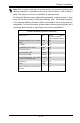
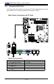
MAC CO DE
JPI2C
JF1
JPW1
U26
J8
J6
J5
J14
1
J13
U61
T-SGPIO1
T-SGPIO2
J24
JLAN2
JLAN1
SPKR1
JBT1
1
JI2C1
1
JI2C2
1
LE4
LE2
LE3
LE7
JPT1
1
JPB
JLED1
1
1
JPUSB1
1
JPL1
1
JPL2
JPG1
JD1
1
FAN2
FAN1
FAN5
1
FAN4
FAN3
J16
PCI1
U2
BAR CO DE
1-2:ENABLE
2-3:DISABLE
JPL2:LAN2 JPL1:LAN1
2-3:DISABLE
1-2:ENABLE
JPB:BMC
JPI2C:PWR I2C
JD1:Buzzer/Speaker
COM2
FLOPPY
DDR3 1066/1333 UDIMM/RDIMM required
VGA
COM1
USB4
JBT1:CMOS CLEAR
SLOT7 PCI-E X8 GEN2
JPT1:TPM
JL1
LAN1
JPUSB1:B/P USB WAKE UP
1-2:ENABLE
2-3:DISABLE
DIMM2B
DIMM2A
USB 10/11
JI2C1/JI2C2
USB2/3
SLOT6 PCI-E X8 GEN2
2-3:Disable
1-2:Enable
JAR:
PSU ALARM RST
CPU
JLED1:Power LED
OFF:Disable
ON:Enable
2-3:Disable
1-2:Enable
REV:1.00
X8SIL
DESIGNED IN USA
2-3:DISABLE
1-2:ENABLE
:CHASSIS INTRUSION
ON
LED LED
PWRHDD
NIC1
NIC2
OH/FFXRST
PWR
I-SA T A3
I-SA T A4
I-SA T A2
I-SA T A1
I-SA T A0
I-SA T A5
SLOT5 PCI-E X4 on X8
SLOT4 PCI 33MHZ
KB/MOUSE
DIMM1B
JPG1: VGA
DIMM1A
JAR
JTPM
JL1
DOM PWR
JPES
1
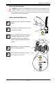
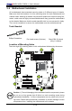
1. Backplane USB 0
2. Backplane USB 1
3. Front Panel USB 10/11
4. Front Panel USB 2/3
(X8SIL-F/X8SIL-V Only)
5. Internal 'Type A' USB 4
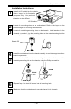
Universal Serial Bus (USB)
Two Universal Serial Bus ports (USB
0/1) are located on the I/O back panel.
Additional four USB connections, USB
2/3 (X8SIL-F/X8SIL-V) and USB 10/11
are used to provide front chassis ac-
cess. USB 4 is a Type A Connector.
(USB Cables are not included). See
the tables on the right for pin deni-
tions.
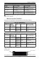
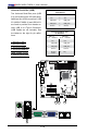
Back Panel USB 0/1
PinDenitions
Pin# Denition Pin# Denition
1 +5V 5 +5V
2 USB_PN1 6 USB_PN0
3 USB_PP1 7 USB_PP0
4 Ground 8 Ground
Front Panel USB 2/3, 10/11
PinDenitions
USB 2, 3
Pin # Denition
USB 10/11
Pin # Denition
1 +5V 6 +5V
2 USB_PN2 7 USB_PN3
3 USB_PP2 8 USB_PP3
4 Ground 9 Ground
5 No Con-
nection
10 Key
4
3
5
1
2