
User`s manual

Chapter 2: Installation
2-19
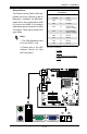
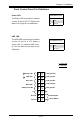
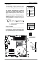
Ethernet Ports
Two Ethernet ports (LAN1/LAN2) are
located next to the VGA port on the IO
Backplane. In addition, an IPMI Dedi-
cated LAN is also located above USB
0/1 ports on the X8SIL-F to provide a
dedicated network connection for IPMI
2.0 support. These ports accept RJ45
type cables.
Notes:
1. The IPMI Dedicated LAN
is for the X8SIL-F only.
2. Please refer to the LED
Indicator Section for LAN
LED information.
LAN Ports
PinDenition
Pin# Denition
1 P2V5SB 10 SGND
2 TD0+ 11 Act LED
3 TD0- 12 P3V3SB
4 TD1+ 13 Link 100 LED
(Yellow, +3V3SB)
5 TD1- 14 Link 1000 LED
(Yellow, +3V3SB)
6 TD2+ 15 Ground
7 TD2- 16 Ground
8 TD3+ 17 Ground
9 TD3- 88 Ground
(NC: No Connection)
1. LAN1
2. LAN2
3.IPMI Dedicated LAN (X8SIL-
F only)
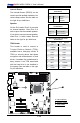
3
1
2
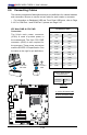
MAC CO DE
JPI2C
JF1
JPW1
U26
J8
J6
J5
J14
1
J13
U61
T-SGPIO1
T-SGPIO2
J24
JLAN2
JLAN1
SPKR1
JBT1
1
JI2C1
1
JI2C2
1
LE4
LE2
LE3
LE7
JPT1
1
JPB
JLED1
1
1
JPUSB1
1
JPL1
1
JPL2
JPG1
JD1
1
FAN2
FAN1
FAN5
1
FAN4
FAN3
J16
PCI1
U2
BAR CO DE
1-2:ENABLE
2-3:DISABLE
JPL2:LAN2 JPL1:LAN1
2-3:DISABLE
1-2:ENABLE
JPB:BMC
JPI2C:PWR I2C
JD1:Buzzer/Speaker
COM2
FLOPPY
DDR3 1066/1333 UDIMM/RDIMM required
VGA
COM1
USB4
JBT1:CMOS CLEAR
SLOT7 PCI-E X8 GEN2
JPT1:TPM
JL1
LAN1
JPUSB1:B/P USB WAKE UP
1-2:ENABLE
2-3:DISABLE
DIMM2B
DIMM2A
USB 10/11
JI2C1/JI2C2
USB2/3
SLOT6 PCI-E X8 GEN2
2-3:Disable
1-2:Enable
JAR:
PSU ALARM RST
CPU
JLED1:Power LED
OFF:Disable
ON:Enable
2-3:Disable
1-2:Enable
REV:1.00
X8SIL
DESIGNED IN USA
2-3:DISABLE
1-2:ENABLE
:CHASSIS INTRUSION
ON
LED LED
PWRHDD
NIC1
NIC2
OH/FFXRST
PWR
I-SA T A3
I-SA T A4
I-SA T A2
I-SA T A1
I-SA T A0
I-SA T A5
SLOT5 PCI-E X4 on X8
SLOT4 PCI 33MHZ
KB/MOUSE
DIMM1B
JPG1: VGA
DIMM1A
JAR
JTPM
JL1
DOM PWR
JPES
1