
User`s manual

Chapter 2: Installation
2-23
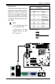
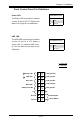
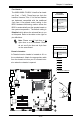
FrontControlPanelPinDenitions
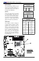
Power LED
The Power LED connection is located
on pins 15 and 16 of JF1. Refer to the
table on the right for pin denitions.
Power LED
PinDenitions(JF1)
Pin# Denition
15 +5V
16 Ground
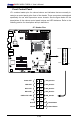
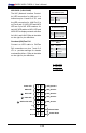
A. PWR LED
B. HDD LED
A
B
Power Button
OH/Fan Fail LED
1
NIC1 LED
Reset Button
2
HDD LED
Power LED
Reset
PWR
LED_Anode+
LED_Anode+
LED_Anode+
LED_Anode+
Ground
Ground
X
X
NIC2 LED
LED_Anode+
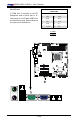
HDD LED
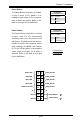
The HDD LED onnections are located
on pins 13 and 14 of JF1. Attach a
cable here to indicate HDD activ-
ity. See the table on the right for pin
denitions.
HDD LED
PinDenitions(JF1)
Pin# Denition
13 +5V
14 HD Active