
User`s manual


Chapter 2: Installation
2-33
B
A
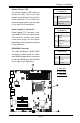
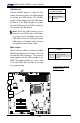
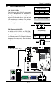
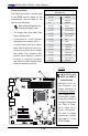
A. VGA Enable
B. TPM Enable
C. Energy Saving Enable
VGA Enable/Disable
Jumper Settings (JPG1)
Both Jumpers Denition
Pins 1-2 Enabled
Pins 2-3 Disabled
VGA Enable
JPG1 allows you to enable or disable
the onboard VGA connector. The default
position is on pins 1 and 2 to enable
VGA. See the table on the right for
jumper settings.
MAC CO DE
JPI2C
JF1
JPW1
U26
J8
J6
J5
J14
1
J13
U61
T-SGPIO1
T-SGPIO2
J24
JLAN2
JLAN1
SPKR1
JBT1
1
JI2C1
1
JI2C2
1
LE4
LE2
LE3
LE7
JPT1
1
JPB
JLED1
1
1
JPUSB1
1
JPL1
1
JPL2
JPG1
JD1
1
FAN2
FAN1
FAN5
1
FAN4
FAN3
J16
PCI1
U2
BAR CO DE
1-2:ENABLE
2-3:DISABLE
JPL2:LAN2 JPL1:LAN1
2-3:DISABLE
1-2:ENABLE
JPB:BMC
JPI2C:PWR I2C
JD1:Buzzer/Speaker
COM2
FLOPPY
DDR3 1066/1333 UDIMM/RDIMM required
VGA
COM1
USB4
JBT1:CMOS CLEAR
SLOT7 PCI-E X8 GEN2
JPT1:TPM
JL1
LAN1
JPUSB1:B/P USB WAKE UP
1-2:ENABLE
2-3:DISABLE
DIMM2B
DIMM2A
USB 10/11
JI2C1/JI2C2
USB2/3
SLOT6 PCI-E X8 GEN2
2-3:Disable
1-2:Enable
JAR:
PSU ALARM RST
CPU
JLED1:Power LED
OFF:Disable
ON:Enable
2-3:Disable
1-2:Enable
REV:1.00
X8SIL
DESIGNED IN USA
2-3:DISABLE
1-2:ENABLE
:CHASSIS INTRUSION
ON
LED LED
PWRHDD
NIC1
NIC2
OH/FFXRST
PWR
I-SA TA3
I-SA TA4
I-SA TA2
I-SA TA1
I-SA TA0
I-SA TA5
SLOT5 PCI-E X4 on X8
SLOT4 PCI 33MHZ
KB/MOUSE
DIMM1B
JPG1: VGA
DIMM1A
JAR
JTPM
JL1
DOM PWR
JPES
1
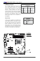
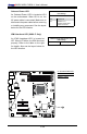
TPM Support Enable
JPT1 allows the user to enable TPM
(Trusted Platform Module) support to im-
prove data integrity and system security.
See the table on the right for jumper set-
tings. The default setting is Enabled.
TPM Support Enable
Jumper Settings
Jumper Setting Denition
1-2 (Default) Enabled
2-3 Disabled
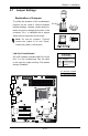
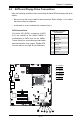
Energy Saving Enable
JPES allows the user to enable the en-
ergy-saving feature of this motherboard.
When set to Enabled, the motherboard
will enter Deep S5 Mode. The default
setting is Disabled (Normal S5 Mode).
Energy Saving Enable
Jumper Settings
Jumper Setting Denition
1-2 Enabled
2-3 (Default) Disabled
C