
User`s manual


2-36
X8SIL/X8SIL-F/X8SIL-V User's Manual
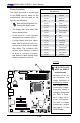
Onboard PWR LED Indicator
LED Settings
LED Color Denition
Off System Off
On System on, or
System off and PWR
Cable Connected
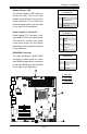
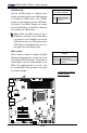
Onboard Power LED
An Onboard Power LED is located at LE4
on the motherboard. When LE4 is on, the
AC power cable is connected. Make sure to
disconnect the power cable before removing
or installing any component. See the layout
below for the LED location.
A. Onboard PWR LED
B. IPMI Heartbeat LED
(X8SIL-F Only)
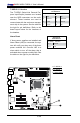
IPMI Heartbeat LED (X8SIL-F Only)
An IPMI Heartbeat LED is located at
LE7. When LE7 blinks, the IPMI functions
properly. Refer to the table on the right
for details. Also see the layout below for
the LED location.
IPMI Heartbeat LED Indicator (LE7)
LED Settings
Green: Blinking IPMI is ready for use
MAC CO DE
JPI2C
JF1
JPW1
U26
J8
J6
J5
J14
1
J13
U61
T-SGPIO1
T-SGPIO2
J24
JLAN2
JLAN1
SPKR1
JBT1
1
JI2C1
1
JI2C2
1
LE4
LE2
LE3
LE7
JPT1
1
JPB
JLED1
1
1
JPUSB1
1
JPL1
1
JPL2
JPG1
JD1
1
FAN2
FAN1
FAN5
1
FAN4
FAN3
J16
PCI1
U2
BAR CO DE
1-2:ENABLE
2-3:DISABLE
JPL2:LAN2 JPL1:LAN1
2-3:DISABLE
1-2:ENABLE
JPB:BMC
JPI2C:PWR I2C
JD1:Buzzer/Speaker
COM2
FLOPPY
DDR3 1066/1333 UDIMM/RDIMM required
VGA
COM1
USB4
JBT1:CMOS CLEAR
SLOT7 PCI-E X8 GEN2
JPT1:TPM
JL1
LAN1
JPUSB1:B/P USB WAKE UP
1-2:ENABLE
2-3:DISABLE
DIMM2B
DIMM2A
USB 10/11
JI2C1/JI2C2
USB2/3
SLOT6 PCI-E X8 GEN2
2-3:Disable
1-2:Enable
JAR:
PSU ALARM RST
CPU
JLED1:Power LED
OFF:Disable
ON:Enable
2-3:Disable
1-2:Enable
REV:1.00
X8SIL
DESIGNED IN USA
2-3:DISABLE
1-2:ENABLE
:CHASSIS INTRUSION
ON
LED LED
PWRHDD
NIC1
NIC2
OH/FFXRST
PWR
I-SA TA3
I-SA TA4
I-SA TA2
I-SA TA1
I-SA TA0
I-SA TA5
SLOT5 PCI-E X4 on X8
SLOT4 PCI 33MHZ
KB/MOUSE
DIMM1B
JPG1: VGA
DIMM1A
JAR
JTPM
JL1
DOM PWR
JPES
1
A
B