
User`s manual


2-38
X8SIL/X8SIL-F/X8SIL-V User's Manual
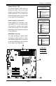
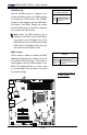
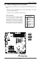
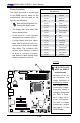
A. Floppy
Floppy Connector
The oppy connector is located next
to the DIMM memory banks on the
motherboard. See the table on the
right for pin denitions.
Floppy Drive Connector
PinDenitions
Pin# Denition Pin # Denition
1 Ground 2 FDHDIN
3 Ground 4 Reserved
5 Key 6 FDEDIN
7 Ground 8 Index
9 Ground 10 Motor Enable
11 Ground 12 Drive Select B
13 Ground 14 Drive Select B
15 Ground 16 Motor Enable
17 Ground 18 DIR
19 Ground 20 STEP
21 Ground 22 Write Data
23 Ground 24 Write Gate
25 Ground 26 Track 00
27 Ground 28 Write Protect
29 Ground 30 Read Data
31 Ground 32 Side 1 Select
33 Ground 34 Diskette
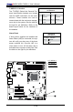
Note the following when con-
necting the oppy cable:
• The oppy disk drive cable has
seven twisted wires.
• A red mark on a wire typically
designates the location of pin 1.
• A single oppy disk drive ribbon
cable has 34 wires and two con-
nectors to provide for two oppy
disk drives. The connector with
twisted wires always connects
to drive A, and the connector
that does not have twisted wires
always connects to drive B.
A
MAC CO DE
JPI2C
JF1
JPW1
U26
J8
J6
J5
J14
1
J13
U61
T-SGPIO1
T-SGPIO2
J24
JLAN2
JLAN1
SPKR1
JBT1
1
JI2C1
1
JI2C2
1
LE4
LE2
LE3
LE7
JPT1
1
JPB
JLED1
1
1
JPUSB1
1
JPL1
1
JPL2
JPG1
JD1
1
FAN2
FAN1
FAN5
1
FAN4
FAN3
J16
PCI1
U2
BAR CO DE
1-2:ENABLE
2-3:DISABLE
JPL2:LAN2 JPL1:LAN1
2-3:DISABLE
1-2:ENABLE
JPB:BMC
JPI2C:PWR I2C
JD1:Buzzer/Speaker
COM2
FLOPPY
DDR3 1066/1333 UDIMM/RDIMM required
VGA
COM1
USB4
JBT1:CMOS CLEAR
SLOT7 PCI-E X8 GEN2
JPT1:TPM
JL1
LAN1
JPUSB1:B/P USB WAKE UP
1-2:ENABLE
2-3:DISABLE
DIMM2B
DIMM2A
USB 10/11
JI2C1/JI2C2
USB2/3
SLOT6 PCI-E X8 GEN2
2-3:Disable
1-2:Enable
JAR:
PSU ALARM RST
CPU
JLED1:Power LED
OFF:Disable
ON:Enable
2-3:Disable
1-2:Enable
REV:1.00
X8SIL
DESIGNED IN USA
2-3:DISABLE
1-2:ENABLE
:CHASSIS INTRUSION
ON
LED LED
PWRHDD
NIC1
NIC2
OH/FFXRST
PWR
I-SA TA3
I-SA TA4
I-SA TA2
I-SA TA1
I-SA TA0
I-SA TA5
SLOT5 PCI-E X4 on X8
SLOT4 PCI 33MHZ
KB/MOUSE
DIMM1B
JPG1: VGA
DIMM1A
JAR
JTPM
JL1
DOM PWR
JPES
1
I M P O R T A N T
NOTE on X8SIL-F
motherboards
Because of an In-
tel l imitati on, the
floppy connector is
disabled by default,
and C-State will au-
tomatically change-
when this setting is
changed. Please see
our FAQ in Chap-
ter 3, Page 3-5 for
more information.
For more on C-State
architecture, please
see page 4-7 of the
BIOS Chapter.