
- SUPER P4SCT SUPER P4SCT+ SUPER P4SCT+II USER'S MANUAL


Chapter 2: Installation
2-13
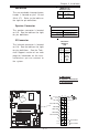
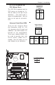
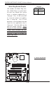
Chassis Intrusion
The Chassis Intrusion header is
designated JL1. See the board
layout in Chapter 1 for the location
of JL1 and the table on the right
for pin definitions.
Pin
Number
1
2
Definition
Intrusion Inpu
t
Ground
Chassis Intrusion
Pin Definitions (JL1)
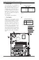
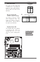
Wake-On-LAN
The Wake-On-LAN header is des-
ignated WOL on the motherboard.
See the table on the right for pin
definitions. You must enable the
LAN Wake-Up setting in BIOS to
use this function. (You must also
have a LAN card with a Wake-On-
LAN connector and cable to use
this feature.)
Pin
Number
1
2
3
Definition
+5V Standby
Ground
Wake-up
Wake-On-LAN Pin
Definitions (WOL)
CPU
478 PGA
MCH
PWR LED
COM2
USB 1/2
P
a
r
a
lle
l P
o
r
t
JPWAKE
WOR
O
H
F
A
N
/
C
H
F
a
n
5
COM 1
VGA
GLAN 1
PCI 1-X
PCI-X 2
PCI -X 3
PCI 2
FLOPPY
BATTERY
BIOS
DIMM 0A (Blue)
Watch Dog
FRONT PANEL CTR
BANK0
BANK1
®
JF1
WOL
I
R
S
u
p
e
r
I/O
Speaker
I-SATA LED
Keylock
USB 3/4
24-pin ATX PWR Conn
S
U
P
E
R
P
4S
C
T
/P
4S
C
T
+
/P
4S
C
T
+
II
GLAN 2
PCI 1
CHS FAN3
Intel's SATA2
KB/Mouse
JPUSB
LA
N
2 Enable
RAGE-XL
+12V 4-pin PWR Conn.
PWR Froce On
(North Bridge)
CHS FAN4
C
P
U
S
p
e
e
d
C
P
U
/
C
H
F
a
n
1
Intel's SATA1
SATA1/5
SATA3/7SATA4/8
VGA Enable
AGP Pro
SMBus
SATA CTLR
GLAN CTLR
82541
CLR CMOS
Hance
Rapids
M-SATA1-2 Enable
Marvell
SATA2/6
ID
E
1
ID
E
2
Ch. Intru.
CHS FAN2
(Marvall's SATA)
Standby LED
LAN CTLR
82547
DIMM 1A (Blue)
DIMM 0B (Black)
DIMM 1B (Black)
Speaker
M- SATA LED
PWR Force On
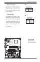
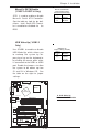
A. Wake-On-LAN
B. Chassis Intrusion
A
B