
Datasheet

Chapter 2: Installation
2-5
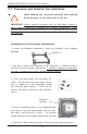
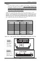
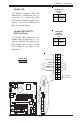
To Install:
Insert module
vertically and
press down
until it snaps
into place.
Pay attention
to the notch.
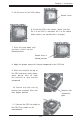
Figure 2-2. Side and Top Views of DDR Module Installation into Slot
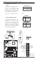
To Remove:
Use your thumbs
gently to push
each release tab
outward to
release the DIMM
from the slot.
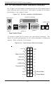
Support
The P4SCT/P4SCT+/P4SCT+II supports Dual channel, ECC/non-ECC,
unbuffered DDR-400/333/266 SDRAM. (Populate DIMM0A,DIMM1A and/
or DIMM0B, DIMM1B with memory modules of the same size/same type
will result in the dual channel, two-way interleaved memory which is
faster than the single channel memory.
Memory Speeds
Host Clock
(MHz)
FSB (MHz) DRAM DATA
RATE (MT/s)
Shown during
POST
100 400 266 DDR266
333 DDR266
400 DDR266
133 533 266 DDR266
333 DDR333
400 DDR333
200 800 266 DDR266
333 DDR320
(*Note)
400 DDR400
(*Note: The BIOS will display 320 due to the limitation of Intel’s chipset).
(*Note: The Canterwood chip supports non-ECC or ECC memory. If ECC
memory is installed, the ECC bits need to be initialized via BIOS before normal
operation. For a 4 GB-Memory and 2.4-GHz P4 system, it will take about 65
seconds for all the ECC bits to be initialized before any video displays. Since
ECC initialization takes time, the Watch Dog Timer Select needs to be set to a
time longer than what the ECC initialization will take.)