
Datasheet

2-10
SUPER P4SCT/P4SCT+/P4SCT+II User's Manual
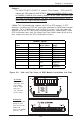
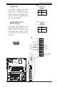
LAN1 LED
Power Button
Overheat LED
1
Reset Button
2
IDE LED
Power On LED
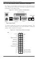
Reset
Pwr
Vcc
Vcc
Vcc
Vcc
Ground
Ground
1920
Vcc
X
Ground
NMI
X
X
X
LAN2 LED
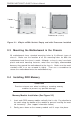
Power_LED Connector
The Power LED connector is lo-
cated on pins 15, 16 of JF1. (*Use
J17 for a 3-pin connector.) This
connection is used to provide LED
indication of power being supplied
to the system. See the table on
the right for pin definitions.
Pin
Number
15
16
Definition
+5V
Ground
Power_LED
Pin Definitions (JF1)
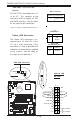
*IDE LED (*See the note
below)
The IDE LED is located on pins 13,
14 of JF1. This connects to the
hard drive LED to display all IDE
and SATA activities. See the table
on the right for pin definitions.
(*Note: This LED is for all IDE and SATA devices )
Pin
Number
7
8
Definition
+5V
HD Active
IDE Pin Definition
Pin
Number
1
2
3
Definition
+5V
Key
Ground
J17
Pin Definitions
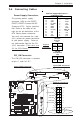
C
P
U
478 PG
A
MCH
PWR LED
COM2
USB 1/2
Par
all
e
l
Port
JPWAKE
WO
R
OH FAN/CH Fan5
COM 1
VGA
GLAN 1
PCI 1-X
PCI-X 2
PCI -X 3
PCI 2
FLOP
PY
BATTERY
BIOS
DIMM 0A (Blue)
Watch Dog
FRONT PANEL CTR
BANK0
BANK1
®
JF1
WOL
I
R
Super I/O
Speake
r
I-SATA LED
Keylock
USB 3/4
24-pin ATX
PWR
Conn
S
UPER P4SCT/P4SCT+/P4SCT+II
GLAN 2
PCI 1
CHS FAN3
Intel's SATA2
K
B
/
M
o
u
s
e
JPUSB
LAN2
E
na
ble
RAGE-XL
+12V 4-pin PWR Conn.
PWR Froce On
(North Bridge)
CHS FAN4
CPU S
peed
CPU
/
C
HFan
1
Intel's SATA1
SATA1/5
SATA3/7
SATA4/8
VGA Enable
AGP Pro
SMBus
SATA CTLR
GLAN CTLR
82541
CLR CMOS
Hance
Rapids
M-SATA1-2 Enable
Marvell
SATA2/6
IDE
1
IDE
2
Ch. Intru.
CHS FAN2
(Marvall's SATA)
Standby LED
LAN CTLR
82547
DIMM 1A (Blue)
DIMM 0B (Black)
DIMM 1B (Black)
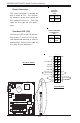
Speake
r
M- SATA LED
PWR Force On
PWR LED
+12V 4-pin PWR Conn.
C
P
U
/C
H
F
a
n
1
FRONT PANEL CTR
JF1
R
CHS FAN3
PWR On LED
IDE LED
PWR LED Connector