
Datasheet


Chapter 2: Installation
2-11
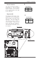
LAN1 LED
Power Button
Overheat LED
1
Reset Button
2
IDE LED
Power On LED
Reset
Pwr
Vcc
Vcc
Vcc
Vcc
Ground
Ground
1920
Vcc
X
Ground
NMI
X
X
X
LAN2 LED
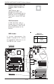
Speaker Connector
The speaker connector is located
on J18. See the table on the right
for pin definitions.
Fucntion
Pin Definition
Speaker: Pin Definition
Pins 1, 4
Pins 3, 4
External Speaker
Internal Speaker
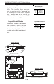
NMI Button
The non-maskable interrupt button
header is located on pins 19 and
20 of JF1. Refer to the table on
the right for pin definitions.
Pin
Number
19
20
Definition
Ground
Control
NMI Button Pin
Definitions (JF1)
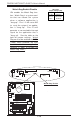
IR Connector
The infrared connector is located
on J16. See the table on the right
for pin definitions. See the Tech-
nical Support section of our web
page for information on the infra-
red devices you can connect to
the system.
Pin
Number
1
2
3
4
5
6
Infrared Pin
Definitions
(J16)
Definition
+5V
CIRRX
IRRX
Ground
IRTX
NC
CPU
478 PGA
MCH
PWR LED
COM2
USB 1/2
Parallel Port
JPWAKE
WOR
OH FAN/CH Fan5
COM 1
VGA
GLAN 1
PCI 1-X
PCI-X 2
PCI -X 3
PCI 2
F
L
O
P
P
Y
BATTERY
BIOS
DIMM 0A (Blue)
Watch Dog
FRONT PANEL CTR
BANK0
BANK1
®
JF1
WOL
IR
Super I/O
Speaker
I-SATA LED
Keylock
USB 3/4
24-pin ATX PWR Conn
S
UPER P4SCT/P4SCT+/P4SCT+II
GLAN 2
PCI 1
CHS FAN3
Intel's SATA2
K
B
/M
o
u
s
e
JPUSB
LAN2 Enable
RAGE-XL
+12V 4-pin PWR Conn.
PWR Froce On
(North Bridge)
CHS FAN4
CPU Speed
CPU/CHFan1
Intel's SATA1
SATA1/5
SATA3/7SATA4/8
VGA Enable
AGP Pro
SMBus
SATA CTLR
GLAN CTLR
82541
CLR CMOS
Hance
Rapids
M-SATA1-2 Enable
Marvell
SATA2/6
IDE1
IDE2
Ch. Intru.
CHS FAN2
(Marvall's SATA)
Standby LED
LAN CTLR
82547
DIMM 1A (Blue)
DIMM 0B (Black)
DIMM 1B (Black)
Speaker
M- SATA LED
PWR Force On
PCI 2
BATTERY
®
Speaker
I-SATA LED
Keylock
USB 3/4
S
UPER
P
RAGE-XL
VGA Enable
SATA CTLR
Speaker
M- SATA LED
FRONT PANEL CTR
JF1
IR
C
HS FAN3
A
2
A
1
S
ATA4/8
S
CHS FAN2
NMI Button
Speaker Connector
IR Connector