
Datasheet


2-12
SUPER P4SCT/P4SCT+/P4SCT+II User's Manual
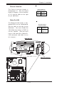
Fan Headers
There are six fan headers on the
P4SCT/P4SCT+/P4SCT+II, which
are designated CPU/Chassis Fan1,
CH Fan 2, CH Fan 3, CH Fan 4,
and Over Heat Fan/CH Fan 5.
(Chassis Fan 3 and Chassis Fan 4
are not monitored by BIOS.) Con-
nect the fan on your CPU heatsink
to the CPU/CH Fan1 header. See
the table on the right for pin defini-
tions.
Fan Header Pin Definitions
(CPU, Chassis and Overheat)
Pin
Number
1
2
3
Definition
Ground (black)
+12V (red)
Tachometer
Caution: These fan headers are DC power.
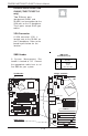
Serial Ports
Two serial ports are included on
the motherboard: COM1(J9) is a
port located beside the mouse/
keyboard ports and COM2(J10) is
a header located on the mother-
board near J20 (Power Connec-
tor). See the table on the right for
pin definitions.
*NC indicates no connection.
Serial Port Pin Definitions
(COM1, COM2)
Pin Number Definition
1 CD
2 RD
3 TD
4 DTR
5 Ground
Pin Number Definition
6 DSR
7 RTS
8 CTS
9 RI
10 NC
Note: Pin 10 is included on the header but not on
the port.
CPU
478 PGA
MCH
PWR LED
COM2
USB 1/2
Parallel Port
JPWAKE
WOR
O
H
FA
N/CH
Fan5
COM 1
VGA
GLAN 1
PCI 1-X
PCI-X 2
PCI -X 3
PCI 2
FLOPPY
BATTERY
BIOS
DIMM 0A (Blue)
Watch Dog
FRONT PANEL CTR
BANK0
BANK1
®
JF1
WOL
IR
Super I/O
Speaker
I-SATA LED
Keylock
USB 3/4
24-pin ATX PWR Conn
S
UPER P4SCT/P4SCT+/P4SCT+II
GLAN 2
PCI 1
CHS FAN3
Intel's SATA2
KB/M
ouse
JPUSB
LA
N
2 E
nable
RAGE-XL
+12V 4-pin PWR Conn.
PWR Froce On
(North Bridge)
CHS FAN4
C
P
U
S
p
eed
CPU
/CH
Fan1
Intel's SATA1
SATA1/5
SATA3/7SATA4/8
VGA Enable
AGP Pro
SMBus
SATA CTLR
GLAN CTLR
82541
CLR CMOS
Hance
Rapids
M-SATA1-2 Enable
Marvell
SATA2/6
IDE1
IDE2
Ch. Intru.
CHS FAN2
(Marvall's SATA)
Standby LED
LAN CTLR
82547
DIMM 1A (Blue)
DIMM 0B (Black)
DIMM 1B (Black)
Speaker
M- SATA LED
PWR Force On
COM Port 1
COM Port 2 CPU/CH Fan 1
CH Fan 2
CH Fan 3
CH Fan 4
OH/CH Fan 5