
Datasheet


Chapter 2: Installation
2-17
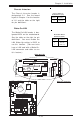
Intel's SATA LED
The header for Intel's SATA LED
is located on J37. This header will
display all Intel's SATA activities.
See the table on the right for pin
definitions.
Intel's SATA LED
Pin Definitions
(J37)
Pin
Number
1
2
3
4
5
Definition
(I-)SATA1
(I-)SATA2
NC
NC
NC
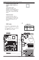
Marvell's SATA LED
(*P4SCT+/ P4SCT+II Only)
The header for Marvell's SATA
LED is located on JS9. This
header will display all Marvell's
SATA activities. See the table on
the right for pin definitions.
Marvell's SATA Pin Definitions
(JS9)
Pin Number Definition
1 (M-)SATA1
2 (M-)SATA2
3 (M-)SATA3
4 (M-)SATA4
5 (M-)SATA
LED Comm
Pin Number Definition
6 NC
7 NC
8 NC
9 NC
10 Key
C
P
U
478 PG
A
MCH
PWR LED
COM2
USB 1/2
P
ar
a
llel
Po
rt
JPWAKE
WO
R
O
H FAN/CH Fan5
COM 1
VGA
GLAN 1
PCI 1-X
PCI-X 2
PCI -X 3
PCI 2
FLO
PPY
BATTERY
BIOS
DIMM 0A (Blue)
Watch Dog
FRONT PANEL CTR
BANK0
BANK1
®
JF1
WOL
I
R
Sup
e
r I/O
Speake
r
I-SATA LED
Keylock
USB 3/4
24-pin ATX
PWR
Conn
S
UPER P4SCT/P4SCT+/P4SCT+II
GLAN 2
PCI 1
CHS FAN3
Intel's SATA2
K
B
/
M
o
u
s
e
JPUSB
LAN2
E
na
ble
RAGE-XL
+12V 4-pin PWR Conn.
PWR Froce On
(North Bridge)
CHS FAN4
C
P
U
Sp
e
e
d
CPU/C
HFan
1
Intel's SATA1
SATA1/5
SATA3/7
SATA4/8
VGA Enable
AGP Pro
SMBus
SATA CTLR
GLAN CTLR
82541
CLR CMOS
Hance
Rapids
M-SATA1-2 Enable
Marvell
SATA2/6
IDE1
IDE2
Ch. Intru.
CHS FAN2
(Marvall's SATA)
Standby LED
LAN CTLR
82547
DIMM 1A (Blue)
DIMM 0B (Black)
DIMM 1B (Black)
Speake
r
M- SATA LED
PWR Force On
PCI 2
FLOPP
Y
BATTERY
®
Speaker
I-SATA LED
Keylock
USB 3/4
S
UPER
CHS FAN4
SATA1/5
VGA Enable
SA
T
IDE1
IDE2
Ch. Intru.
(Marval
Speaker
M- SATA LED
Intel SATA LED
Marvell SATA LED
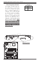
Standby Power LED
The Standby Power LED Indicator
is located on LE2. When the
Standby PWR LED is on, it indi-
cates the system standby power
is on.
PCI 1-X
PCI-X 2
PCI -X 3
PCI 2
BATTERY
®
W
U
S
E
R P4SCT/P4SCT+/P4SC
T
PCI 1
L
A
N
2
E
n
a
b
le
RAGE-XL
AGP Pro
SMBu
s
GLAN CTLR
82541
Standby LED
Speaker
Standby PWR LED