
Datasheet


2-20
SUPER P4SCT/P4SCT+/P4SCT+II User's Manual
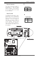
Watch Dog Enable/Disable
JP8 enables the Watch Dog func-
tion. Watch Dog is a system moni-
tor that can reboot the system
when a software application is
"hung up". Pins 1-2 will cause WD
to reset the system if an applica-
tion is "hung up". Pins 2-3 will
generate a non-maskable interrupt
signal for the application that is
"hung up". See the table on the
right for jumper settings. Watch
Dog can also be enabled via BIOS.
(*Note, when enabled, the user
needs to write his own application
software in order to disable the
Watch Dog Timer.)
Jumper
Position
Pins 1-2
Pins 2-3
Open
Definition
WD to Reset
WD to NMI
Disabled
Watch Dog
Jumper Settings (JP8)
CPU
478 PGA
MCH
PWR LED
COM2
USB 1/2
Parallel Port
JPWAKE
WOR
OH FAN/CH Fan5
COM 1
VGA
GLAN 1
PCI 1-X
PCI-X 2
PCI -X 3
PCI 2
F
L
O
P
P
Y
BATTERY
BIOS
DIMM 0A (Blue)
Watch Dog
FRONT PANEL CTR
BANK0
BANK1
®
JF1
WOL
IR
Super I/O
Speaker
I-SATA LED
Keylock
USB 3/4
24-pin ATX PWR Conn
S
UPER P4SCT/P4SCT+/P4SCT+II
GLAN 2
PCI 1
CHS FAN3
Intel's SATA2
K
B
/M
o
u
s
e
JPUSB
LAN2 Enable
RAGE-XL
+12V 4-pin PWR Conn.
PWR Froce On
(North Bridge)
CHS FAN4
CPU Speed
CPU/CHFan1
Intel's SATA1
SATA1/5
SATA3/7SATA4/8
VGA Enable
AGP Pro
SMBus
SATA CTLR
GLAN CTLR
82541
CLR CMOS
Hance
Rapids
M-SATA1-2 Enable
Marvell
SATA2/6
IDE1
IDE2
Ch. Intru.
CHS FAN2
(Marvall's SATA)
Standby LED
LAN CTLR
82547
DIMM 1A (Blue)
DIMM 0B (Black)
DIMM 1B (Black)
Speaker
M- SATA LED
PWR Force On
CPU
PWR LED
COM2
USB 1/2
JPWAKE
WOR
Watch Dog
p
er I/O
24-pin ATX PWR Conn
KB/Mouse
JPUSB
+12V 4-pin PWR Conn.
PWR Froce On
C
P
U
/C
H
F
a
n
1
PWR Force On
Watch Dog Enable