
Datasheet


Chapter 2: Installation
2-21
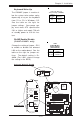
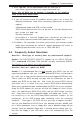
GLAN2 Enable/Disable
(*P4SCT+/P4SCT+ only)
Change the setting of jumper JPL2
to enable or disable the onboard
LAN on the motherboard. See the
table on the right for jumper set-
tings. The default setting is En-
abled. (For LAN1, please change
the setting in the BIOS.)
Jumper
Position
Pins 1-2
Pins 2-3
Definition
Enabled
Disabled
LAN
Enable/Disable
Jumper Settings
(JPL2-*P4SCT+)
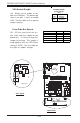
Keyboard Wake-Up
The JPWAKE jumper is used to al-
low the system to be woken up by
depressing a key on the keyboard
from S1 or S3 in Windows OS.
See the table on the right for
jumper settings. Your power sup-
ply must meet ATX specification
2.01 or higher and supply 720 mA
of standby power to use this fea-
ture.
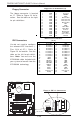
CPU
478 PGA
MCH
PWR LED
COM2
USB 1/2
Parallel Port
JPWAKE
WOR
OH FAN/CH Fan5
COM 1
VGA
GLAN 1
PCI 1-X
PCI-X 2
PCI -X 3
PCI 2
F
L
O
P
P
Y
BATTERY
BIOS
DIMM 0A (Blue)
Watch Dog
FRONT PANEL CTR
BANK0
BANK1
®
JF1
WOL
IR
Super I/O
Speaker
I-SATA LED
Keylock
USB 3/4
24-pin ATX PWR Conn
S
UPER P4SCT/P4SCT+/P4SCT+II
GLAN 2
PCI 1
CHS FAN3
Intel's SATA2
K
B
/M
o
u
s
e
JPUSB
LAN2 Enable
RAGE-XL
+12V 4-pin PWR Conn.
PWR Froce On
(North Bridge)
CHS FAN4
CPU Speed
CPU
/CHFan1
Intel's SATA1
SATA1/5
SATA3/7SATA4/8
VGA Enable
AGP Pro
SMBus
SATA CTLR
GLAN CTLR
82541
CLR CMOS
Hance
Rapids
M-SATA1-2 Enable
Marvell
SATA2/6
IDE1
IDE2
Ch. Intru.
CHS FAN2
(Marvall's SATA)
Standby LED
LAN CTLR
82547
DIMM 1A (Blue)
DIMM 0B (Black)
DIMM 1B (Black)
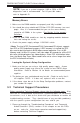
Speaker
M- SATA LED
PWR Force On
COM2
USB 1/2
JPWAKE
KB/Mouse
JPUSB
BAN
K
®
S
UPER P4SCT/P4SCT+/P4SCT+II
L
A
N
2
E
n
a
b
le
RAGE-XL
VGA En
a
GLAN CTLR
82541
Stan
Speaker
GLAN Enable
Keyboard Wake-UP Enable
Jumper
Position
1-2
2-3
Definition
VCC5V
Keyboard Wake-Up
Jumper Settings (JPWAKE)
VCC5V
Standby