
Datasheet
2-14
PDSLA/PDSLE User's Manual
S
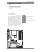
UPER DSLA/PDSLE
PCI-E x1
®
LGA 775 Processor
KB/MS
Parallel Port
COM1
VGA
USB
3/4/5/6
USB1/2
JF
US
B
1
Fan3
Clock
945G/P
(Lakeport)
North Bridge
PCI-E x16
LAN
CTRL
JPL1
GLAN Enable
CD inAux.In
AC97
COM2
BIOS
CL CMOS
JL1
WOL
I-SATA0
FP CTRL
Fan
2
JF 1
Buzzer
I
D
E
2
4
-
Pi
n
ATX PW R
Su per I/
O
F/P USB7/8
ICH7
J9
DIMM#1A
DIMM#2A
DIMM#1B
DIMM#2B
Floppy
Audio
JBT1
J3
J
2
7
J40
South Bridge
J13
J45
J11
J44
JG1
J31
J30
Battery
PCI#4 -33MHz
4-Pin ATX PWR
J41
J28
JPUSB1
JF
US
B
2
J
7
J
1
PCI-E x1
J8
P
C
I
4
PCI#3 -33MHz
PC I3
P
C
I
2
PCI#2-33MHz
PCI#1-33MHz
PC
I
1
J
P
1
J
P2
JPU S
B
2
F
/
P
USB Wa
ke-up
J43
I-SATA1
I-SATA2
I-SATA3
D
24
JWD
JLED
L
E1
J
W
OR
RJ45
Fan1/CPU
Slot#1
Slot#2
Slot#3
Slot#5
Slot#4
Slot#6
Slot#7
FP Aud
J12
(*PDSLA )
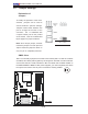
Chassis Intrusion
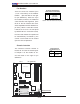
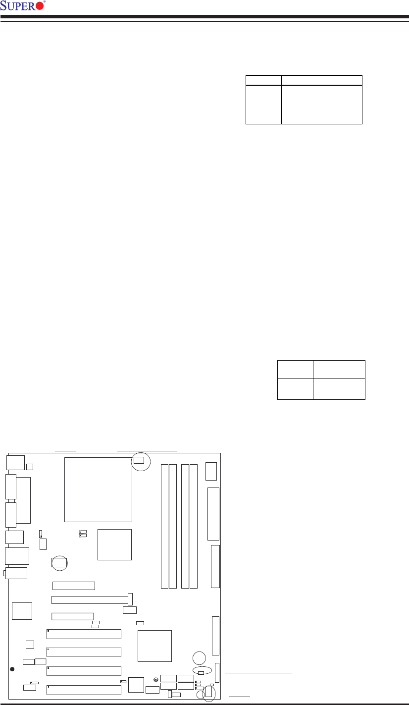
The Chassis Intrusion header is
located at JL1.See the board layout
in Chapter 1 for the location of JL1
and the table on the right for pin
defi nitions.
Pin
Number
1
2
Definition
Intrusion Input
Ground
Chassis Intrusion
Pin Definitions (JL1)
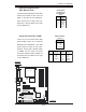
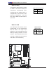
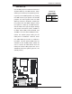
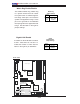
Fan Headers
There are three fan headers (Fan
1, Fan 2 and Fan3) on the PDSLA/
PDSLE. (See the table on the right
for pin defi nitions.) These are 4-pin
fan headers; however, the traditional
3-wire fans are also supported. (Pins
#1-#3 of the fan headers are back-
ward compatible with the traditional 3-
pin fans.) When a 3-wire fan is used,
it will be set to run at the full speed
by default. When a 4-wire fan is used,
the CPU and chassis fan speeds will
be automatically controlled by the
control circuit inside the fan based
upon the CPU temperature.
Fan Header Pin Definitions
(CPU, Chassis and Overheat)
Pin#
1
2
3
Definition
Ground (black)
+12V (red)
Tachometer
Caution: These fan headers use DC power.
4PWM_Control
Chassis Intrusion
Fan 2
Fan 1(CPU Fan)Fan 3