
Datasheet

2-24
PDSLA/PDSLE User's Manual
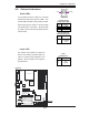
2-9 Parallel Port, Floppy Drive, and Hard Drive
Connections
Use the following information to connect the fl oppy and hard disk drive cables.
• The fl oppy disk drive cable has seven twisted wires.
• A red mark on a wire typically designates the location of pin 1.
• A single fl oppy disk drive ribbon cable has 34 wires and two connectors to provide
for two fl oppy disk drives. The connector with twisted wires always connects to
drive A, and the connector that does not have twisted wires always connects to
drive B.
• The 80-wire ATA100/66 IDE hard disk drive cable that came with your system
has two connectors to support two drives. This special cable should be used
to take advantage of the speed this new technology offers. The blue connector
connects to the onboard IDE connector interface and the other connector(s) to
your hard drive(s). Consult the documentation that came with your disk drive
for details on actual jumper locations and settings for the hard disk drive.
S
UPER DSLA/PDSLE
PCI-E x1
®
LGA 775 Processor
KB/MS
Parallel Port
COM1
VGA
USB
3/4/5/6
USB1/2
JF
U
S
B
1
Fan3
Clock
945G/P
(Lakeport)
North Bridge
PCI-E x16
LAN
CTRL
JPL1
GLAN Enable
CD inAux.In
AC97
COM2
BIOS
CL CMOS
JL1
WOL
I-SATA0
F
PCT
R
L
Fa
n2
J
F1
Buzzer
I
D
E
24
-P
i
nA
T
XPW
R
Su
p
e
r
I
/
O
F/P USB7/8
ICH7
J9
DIMM#1A
DIMM#2A
DIMM#1B
DIMM#2B
Floppy
Audio
JBT1
J3
J
27
J40
South Bridge
J13
J45
J11
J44
JG1
J31
J30
Battery
PCI#4 -33MHz
4-Pin ATX PWR
J41
J28
JPUSB1
J
F
U
S
B
2
J
7
J
1
PCI-E x1
J
8
PC
I
4
PCI#3 -33MHz
P
C
I
3
P
C
I
2
PCI#2-33MHz
PCI#1-33MHz
PC
I1
J
P
1
J
P
2
JP
U
S
B
2
F
/
P
USB Wa
k
e-
up
J43
I-SATA1
I-SATA2
I-SATA3
D2 4
JWD
JLED
LE 1
J
W
O
R
RJ45
Fan1/CPU
Slot#1
Slot#2
Slot#3
Slot#5
Slot#4
Slot#6
Slot#7
FP Aud
J12
(*PDSLA )
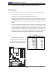
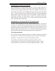
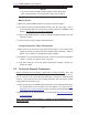
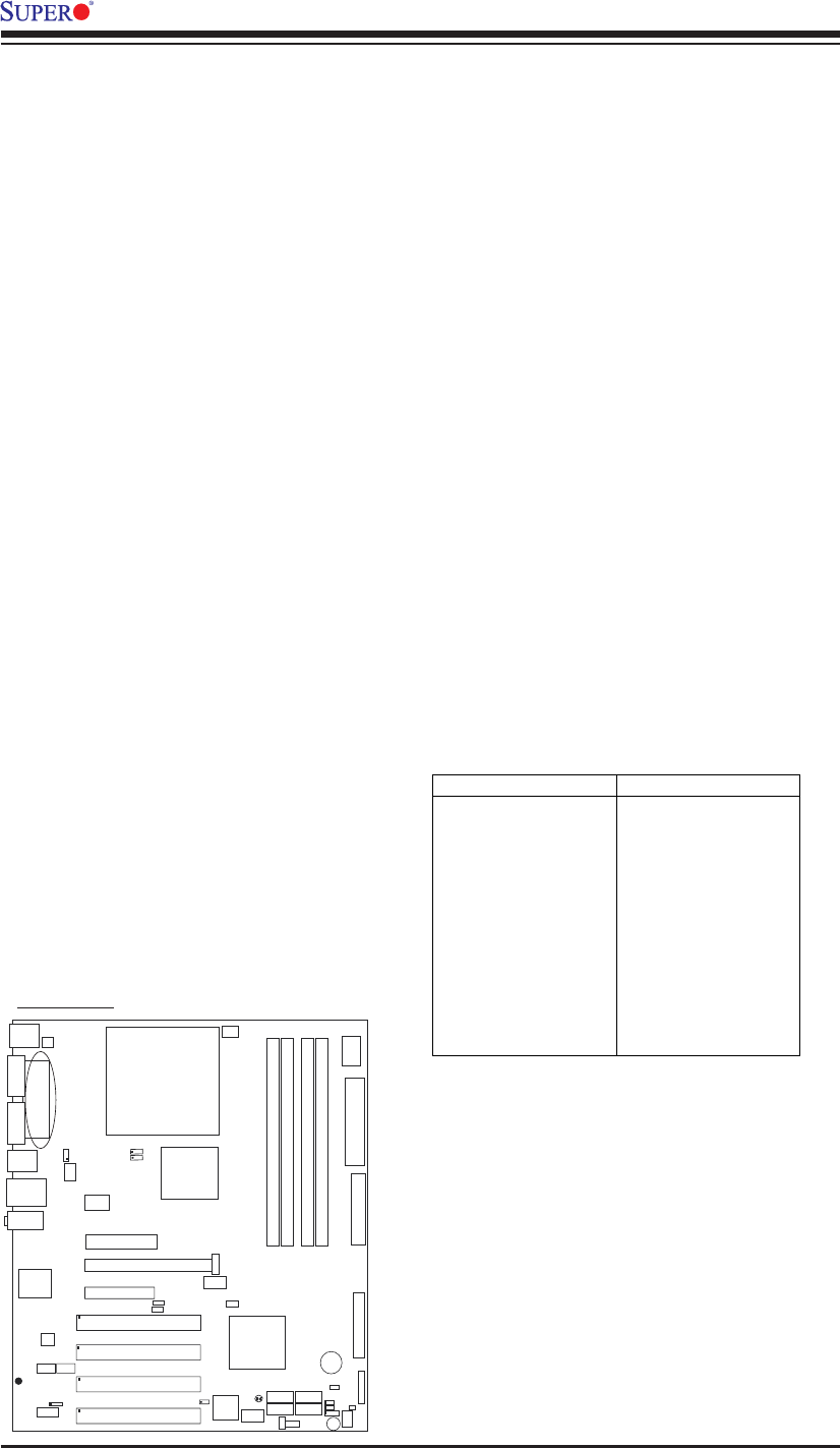
Parallel Port Connector
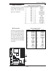
The parallel port is located at J30. Re-
fer to Figure 2-3 for location. See the
table on the right for pin defi nitions.
Pin Number Function
1 Strobe-
3 Data Bit 0
5 Data Bit 1
7 Data Bit 2
9 Data Bit 3
11 Data Bit 4
13 Data Bit 5
15 Data Bit 6
17 Data Bit 7
19 ACK
21 BUSY
23 PE
25 SLCT
Pin Number Function
2 Auto Feed-
4 Error-
6 Init-
8 SLCT IN-
10 GND
12 GND
14 GND
16 GND
18 GND
20 GND
22 GND
24 GND
26 NC
Parallel (Printer) Port Pin Definitions
(J30)
Parallel Port