
Datasheet


Chapter 2: Installation
2-7
S
UPER PDSM4+
®
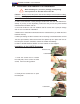
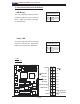
Figure 2-2. DDR 2 Installation
To Install: Insert module vertically and press down until it
snaps into place. Pay attention to the alignment notch at
the bottom.
DDR S
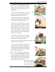
To Remove:
Use your thumbs to
gently push the release
tabs near both ends of
the module. This should
release it from the slot.
DDR
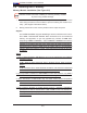
Possible System Memory Allocation & Availability
System Device Size Physical Memory
Remaining (-Available)
(4 GB Total System Memory)
Firmware Hub fl ash memory
(System BIOS)
1 MB 3.99
Local APIC 4 KB 3.99
Area Reserved for the chipset 2 MB 3.99
I/O APIC (4 Kbytes) 4 KB 3.99
PCI Enumeration Area 1 256 MB 3.76
PCI Express (256 MB) 256 MB 3.51
PCI Enumeration Area 2 (if
needed) -Aligned on 256-MB
boundary-
512 MB 3.01
VGA Memory 16 MB 2.85
TSEG 1 MB 2.84
Memory available to OS and
other applications
2.84